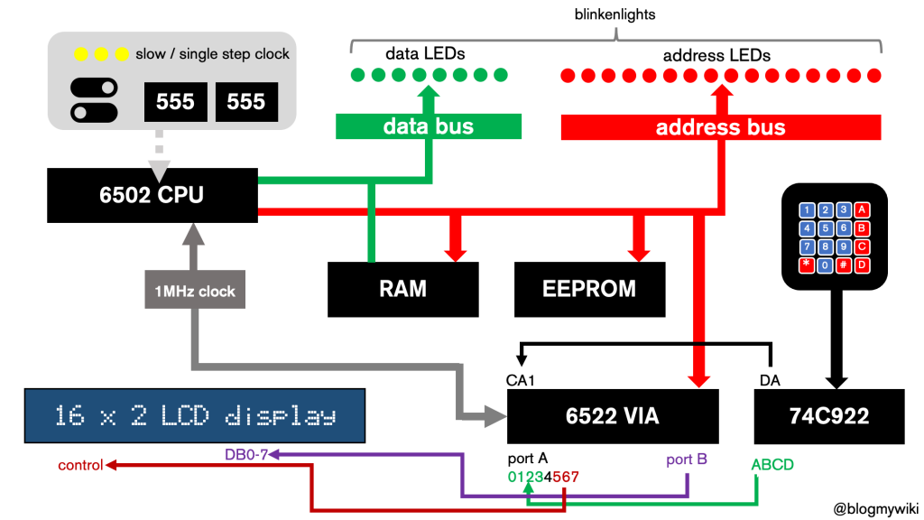
6502 breadboard computer part 4 – first monitor

I’ve been following Ben Eater’s tutorials to make a breadboard computer based around the classic 1970s processor, the 6502. This CPU was used in many classic 8-bit computers including the Apple 2, BBC Micro, Atari VCS as well as the first two computers I ever used, the Kim-1 and the Commodore PET.

I’ve pretty much caught up with Ben’s tutorials now, and reached a point where I’m probably going to diverge from his project. My aim is to make a computer like a Kim-1 or Acorn System 1: a single-board, self-contained computer with a simple display that you can program using machine language on a hexadecimal keypad.

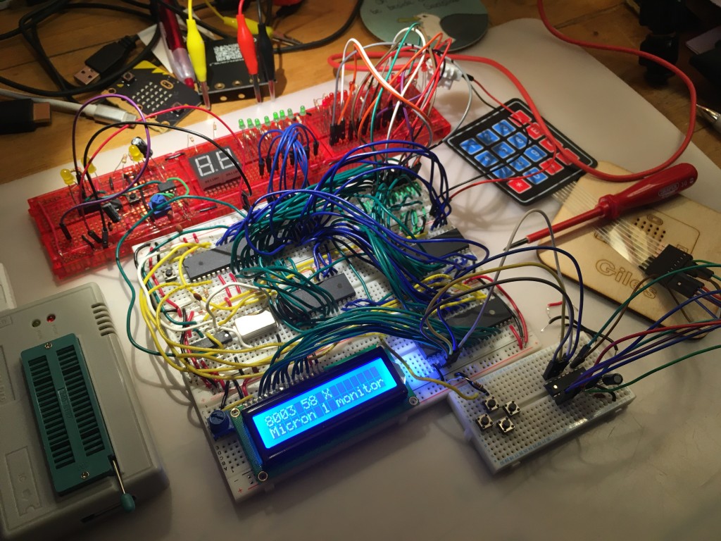
photo of breadboard computer

As a start, I managed to create a program that displays the contents of memory locations. On the first line of the display it shows the address, the contents of that location in hex and then an ASCII representation of the byte in question. You step forwards through the program using a button connected just like Ben Eater’s counter button.

It’s a very small step towards a working monitor program, but quite pleasing to have made. I decided just to start at address #8000 – the ROM – because I know what’s in the ROM and can check the results against the display. Obviously eventually this will cover RAM addresses and allow you to enter new code and run it.

This program only scrolls through 256 locations, but I suspect that’ll be enough for hand-entered machine code programs. I’m unlikely to add any storage devices to this computer, unless anyone has a spare punch tape reader…

Watch the video above to find out more about how it works and find my source code here: https://github.com/blogmywiki/6502

Next step: add a hex keypad!

Posts in this series:
Part 5
Part 4 – you’re here!
Part 3
Part 2
Part 1

Posted in computers | Tagged , | Leave a comment

6502 breadboard computer: part 3 – the return

I last posted way back in October 2020 about my progress with my Ben Eater-style 6502 breadboard computer. Having my own Kim-1 or Acorn System 1 type single board computer was a childhood dream, and several decades later I was building my own, finally feeling I could look that kid in my school computer club who built his own SC/MP-based computer in the eye. Finally. Forty years later. But, finally.

I had managed to connect an EEPROM which I programmed with one of Ben’s programs, and I made a simple clock from some 555 timers that allowed me to single-step or run programs very slowly. I don’t have an Arduino Mega to use for debugging, so I diverged from Ben’s layout by adding 8 green LEDs across the data bus and 16 red LEDs across the address bus. This decision proved to be one of my better ones.

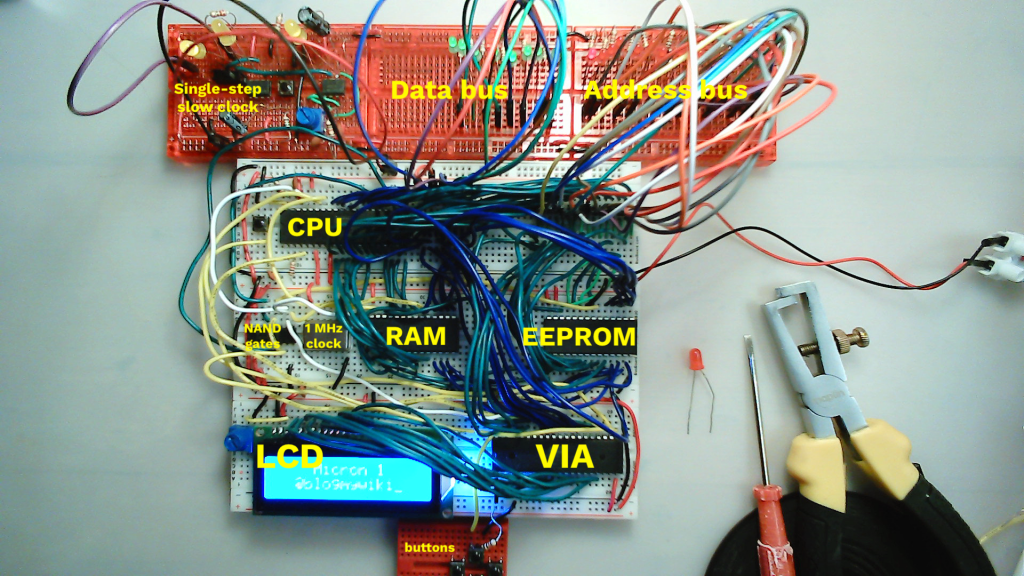
new layout of my 6502 breadboard computer

I added a 65C22 VIA (versatile interface adaptor) and managed to get text to print out on an LCD display. I then decided to rejig the layout a bit to give better access to my data and address busses, and to put the EEPROM in a more accessible place – and that’s when disaster struck.

Nothing worked any more. I could not fix it. I decided I had used the wrong wires, damaged the breadboard, broken something fatally and put it away in a box and left it for a few months.

Picking it up again, I’ve now got it working, added RAM so that you can use the stack, and hence use subroutines. You can’t use subroutines in 6502 assembly language without RAM, because it puts the return address on the stack, and without RAM you have no stack!

I also added a 1 MHz crystal oscillator clock, and today I got interrupts working. I didn’t bother with Ben Eater’s binary to decimal conversion code, I just made it print a different piece of text when you press a button. But it works! I now want to add more buttons, and I know that involves port A on the VIA, but I’ve caught up with Ben Eater now, I need him to make some more videos!

Some words of advice to those of you thinking of making a breadboard computer from scratch:

It’s a good idea!
I’ve re-learnt and learnt some more assembly language, debugged a program literally bit-by-bit – you can’t get closer to the metal than that! I’ve also discovered how CPU interrupts work, and generally found working with fundamental building blocks of hardware and software very satisfying. And yes, resilience… debugging in binary, for an hour… oddly therapeutic.

Slave to the layout
You’re probably better off following Ben’s layout slavishly if you’re new to this. But…

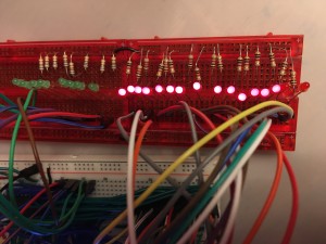
debugging with blinkenlightsBlinkenlights are good
Adding data and address bus blinkenlights is very useful, especially if you don’t have an Arduino Mega to monitor the ports. You could probably add them on separate breadboards and keep Ben’s layout if you’re clever with the wiring. I only fixed my faulty board by single-stepping through a program, and reading every address and piece of data in binary, converting it to hex and decoding it. I discovered that my program wasn’t ever returning from a subroutine, meaning a likely RAM problem. And sure enough, I found a loose wire on the RAM chip. It took me an hour, and I now can read LDA and STA instructions in binary, but it worked. I hadn’t broken anything fatally, it was just a loose wire. Plus, blinkenlights are cool.

Burning EEPROMs
You get to burn EEPROMs. Burning EEPROMs is magic. It’s cool. And you don’t even need UV light to erase them any more.

How do you make your breadboards look so messy?
Watch Ben’s video on how he makes his breadboards so neat. He hadn’t posted it when I started. That’s my excuse.

Like clockwork
Hmm, the clock. I skimped on my clock design, thinking I knew best. Sure I have no logic probe, no oscilloscope, no Arduino Mega to read the busses, but how hard could a darn clock be to make, right?

Well, here’s the thing. As soon as I added the 1 MHz crystal clock, things just started working, well, not just faster (obviously), but better. More reliably. I still get the occasional glitch, but generally my computer seems to work so much better now.

So I now think a lot of the problems I had earlier were with my clock, not giving clean pulses. So if you want to build a clock that allows single-stepping and variable slow speeds (which I think is essential for this kind of project, for learning and debugging), then put in the effort and build a nice clock. Listen to Ben. Even if you think his design is over-engineered.

Where does it go from here?
Not down to the lake, I fear.
Ideas…
- Add moar buttons. No idea how to code them!
- Add a hex display to the data bus – Ben’s video on using EEPROMs to replace a squillion logic gates is very cool. The chip he uses is now obsolete, what would be a good replacement?
- Eventually some kind of monitor program and a hex keypad at least. This is a very far-off goal.
- Add a thermal printer, Aim-65 style.

Code
My modified versions of Ben Eater’s assembly language programs can be found here: https://github.com/blogmywiki/6502

Posted in computers, hardware | Tagged , | 2 Comments

The distraction of distraction-free word processors

I’m currently not writing at least three books. At least one of them, I am convinced, is an amazingly good idea. I’ve written a dozen chapters, at least one of which doesn’t make me cringe when I read it back, but when it comes to the actual paperwork of finishing one… it just doesn’t happen.

The Freewrite

Of course a bad workman blames his tools, so when the Freewrite distraction-free word processor came out a few years ago, I was smitten. It’s a self-contained, portable word processor with an e-Ink display (I love e-Ink displays, they seem indistinguishable from magic to me) that allows you to type and backs up your work to the cloud via wifi but does not allow you to browse the web, Twitter etc, hence ‘distraction-free’. But it’s expensive. Way too expensive for what it is at around $600 – though it is currently on sale for less. As this review points out, you could buy a cheap laptop and a copy of Scrivener and still have money left over to buy a whole other laptop if you break the first one. I think the slowness of the eInk display updating as you type would also be a killer for me. My typing is poor, I really do like to correct typos as I go.

I’ve discovered that there’s no better distraction from writing than researching distraction-free word processors. Here are some personal boxes any solution needs needs to tick:

The wish list

  • Constant on-screen word count – essential
  • Inexpensive
  • Portable
  • Nice clacky keyboard
  • Rich text format editing – italics and bold are a must, ability to change text size and font not so much.
  • Default text size should be large or able to make it large for my poor eyesight.
  • Save in .rtf for similar format so docs can be opened easily by many other apps
  • Paste unformatted text by default
  • Pale yellow page background, not white – or customisable
  • Left, right, centre align options
  • Icons on toolbar not necessary, can just use keyboard shortcuts and menu
  • Show clearly if file is currently unsaved
  • Open by default with last document open
  • Smart quotes
  • Possible cloud backup but it could just save in a Dropbox folder
  • Possible FTP backup
  • Possible timestamp save for keeping each version – option perhaps? Every save gets a new date and timestamp.
  • Images probably not required for fiction
  • Tables probably not required for fiction
  • Runs full-screen

There are lots of apps out there, this is not an exhaustive list by any means, but here are some alternatives to the Freewrite that I’ve considered:

Pen and paper

When the Freewrite was first announced and I was swooning over it on Twitter, someone sent me a photo of a notepad and a biro with the caption ‘my ultimate distraction-free word processor’. And they have a point. Only the other day I read that Sylvia Townsend Warner ‘began her self-proclaimed “accidental career” as a poet after she was given paper with a “particularly tempting surface” and who wrote her first novel, Lolly Willowes; or, The Loving Huntsman (1926), because she “happened to find very agreeable thin lined paper in a job lot.”’ [https://www.britannica.com/biography/Sylvia-Townsend-Warner]

Would that it were so simple.

I need to be able to edit, process text. I need it to be backed up. It’ll need typing up eventually, so although pen and paper is great for jotting down ideas, I am going to eschew the methods of all those great writers, including Muriel Spark, who always wrote in the same kind of notebook from an Edinburgh stationers, all those writers who just need a good pen, good stationery and start writing at the beginning and keep going until they finish.

So I really do need a gadget.

Coding my own: WoolfWrite

How hard could it be to write a word processor? Not actually that hard, I discovered.

The Freewrite was originally called Hemingwrite, so years ago I fantasised a cheap gadget called WoolfWrite in response. More recently I decided to explore coding one in Python using the simple GUI tool guizero, and here’s how far I have got with it: https://github.com/blogmywiki/woolf-write.

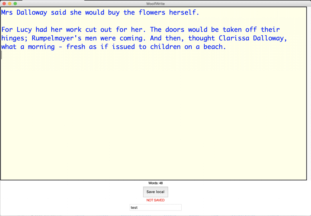
WoolfWrite screenshot

There’s plenty this does not do, it’s plain text-only for example so no bold or italics, but it ticks a few important boxes: on-screen constant word count, large text, no distracting bells and whistles, it warns you when your work is unsaved. The code is pretty simple and if you know even a little bit of Python you can modify this to suit your needs and it’ll run on pretty much any Mac, Windows or Linux machine with Python 3 and guizero installed. If you run it in a Dropbox folder, for example, that could even look after the cloud backups for you.

WordGrinder

Now this found a place in my heart when I discovered that this text editor that runs in a terminal window was written by someone as a distraction from writing a novel. Its author, David Given, is a man after my own heart.

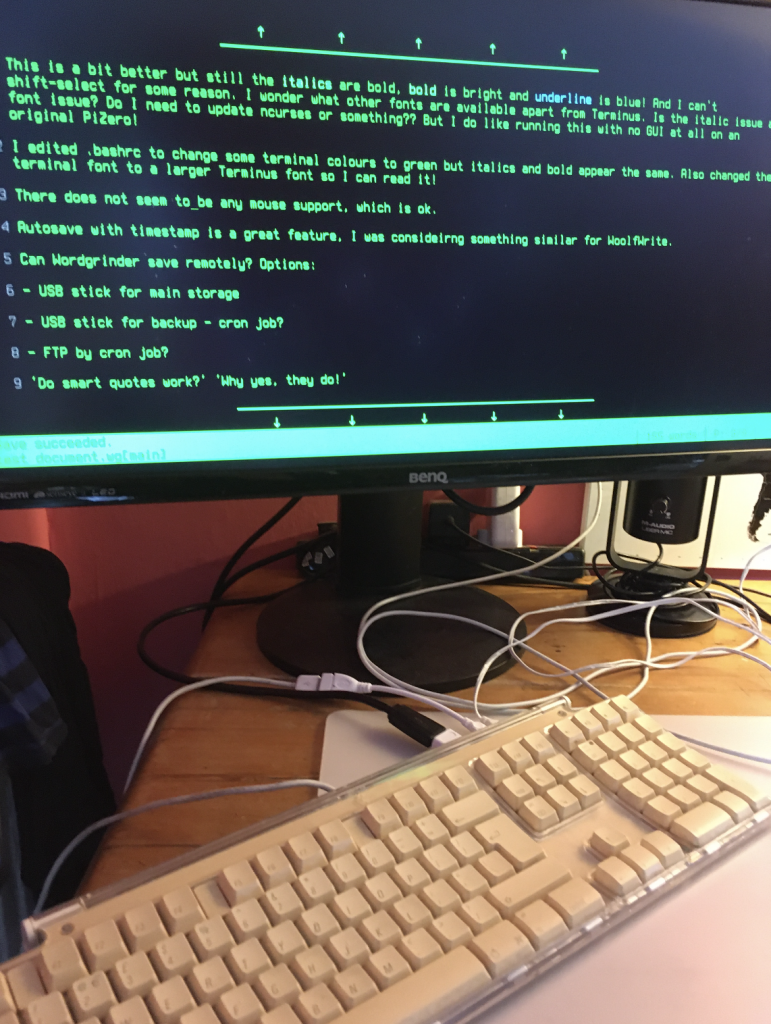
WordGrinder on a PiZero

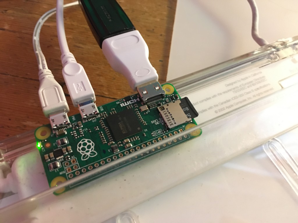
WordGrinder ticks a lot of boxes: it’s fuss-free, and although it’s intended to be run in a window on your desktop, I managed to get an old Raspberry Pi Zero to boot straight to it with no GUI installed at all (pictured below stuck to the underside of a nice old clacky Apple USB keyboard). The major drawback so far is bot being able to get italics to display on either my Mac or on the Pi – indeed on the Pi italics and bold show up the same, which is not great, but I was able to fiddle with a few settings on the computer to get it to display the text in a lovely retro green reminiscent of the Amstrad PCW word processor. And this boots fast using DietPi as its OS.

piZero stuck to keyboard

I love the timestamped auto-save feature, I considered something very similar for WoolfWrite but there are some drawbacks – no cloud backup yet, though maybe a cron job and FTP could work, or perhaps just adding a USB stick for backup. It also uses an esoteric file format rather than RTF or similar, but it can export in various different useful file formats.

If I can fix the italics issue on a GUI-less PiZero and sort out some backup, then this is an insanely cheap solution. The PiZero was a freebie with a magazine and was unused, and the keyboard was also junk. With a small HDMI display I’d have something close to this intriguing home-made version of the Freewrite: https://www.instructables.com/FeatherQuill-34-Hours-of-Distraction-Free-Writing/ .

I’d love to tweak WordGrinder myself, but that’s beyond my coding skills just now as it’s written in C. Which brings me to…

Code or modify my own using Python / PyQT

I did actually get quite far with following this tutorial and modifying the code to suit my needs, which I could do because it’s written in Python. It’s tantalisingly close to what I want, but PyQT is a bit of a heavy dependency and I found this project’s native HTML file format a bit infuriating – although a kind soul on Twitter helped me work out how to export the text to RTF format. (I did want to add RTF format to WoolfWrite, but heavens RTF is a weird format when you look inside it!)

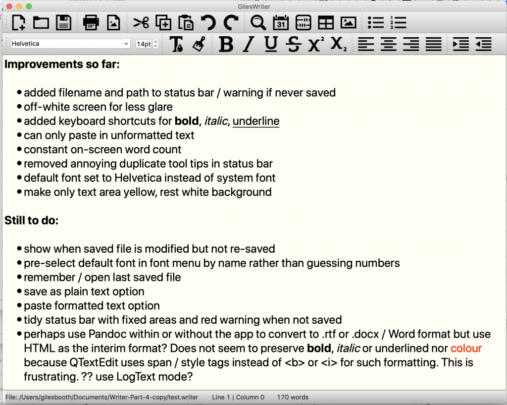
I may come back to this and do a proper write-up of how I stripped this down and made it do more of the things I wanted (like adding a constant on-screen word count, basic formatting keyboard shortcuts and filename display) and fewer of the things I didn’t (e.g. removed infuriatingly duplicated tool-tips and made it paste unformatted text by default – you have no idea how happy the latter made me! All apps and OSs should paste unformatted text by default, you almost always want it to match the destination not the source.)

gileswrite screenshot

.

Google Drive or Dropbox Paper
Google Drive is what I currently use for creative writing and there’s a lot to be said for it, though obviously both of these require internet access and a laptop and all the distractions that affords. Dropbox Paper is nice because its formatting is so limited – for example you can’t change font, and I strongly approve of that, but its chirpy messages when you open a new document annoy me so much that I’ve started making my own sarcastic ones for WoolfWrite. Also Dropbox Paper has limited file export options and frequently tells me I’ve lost my connection when I know my wifi and broadband are just fine, so I’m ruling it out for the great novel project.
Who do you think you are? Ernest Bleeding Hemingway?

Just use the laptop you already have, turn off the damn internet and write

I admit it’s hard to argue against this, and numerous free and paid-for distraction writing apps are out there for you to use, though I couldn’t find one that did precisely what I wanted, which is why I started trying to write or modify my own. A cheap old netbook and some version of either the Python PyQT app or WordGrinder could well be the way to go.

Remember, a bad workman blames his tools.

A writer writes, always.

The night was hot, wait no, the night, the night was humid. The night was humid, no wait, hot, hot. The night was hot. The night was hot and wet, wet and hot. The night was wet and hot, hot and wet, wet and hot; that’s humid. The night was humid.

“Chapter 1. It was a dark and stormy night…”

Posted in computers, literature, lowendmac, Raspberry Pi | Tagged , , | Leave a comment

Make a simple calculator with guizero & Python

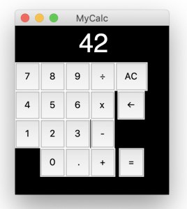
GUI calculator screenshotMaking your own apps, even simple ones, with a GUI still seems to be surprisingly tricky, and this makes it hard to teach, especially if you want to build an app that will run standalone, or near-standalone, on a real computer.

Python is a very popular language for teaching and developing, but its default library for making GUIs, tkinter, is pretty scary and horrible. I have built a few apps for touch screens using it: a radio, an audio play-out system for radio or theatre and a similar cartwall.

Tkinter does give you a lot of control over layout, but I do think it’s way too hard for a beginner, especially a student who’s just getting some confidence with Python and wants to make a ‘real’ app with buttons and widgets.

What is guizero?

This is where guizero comes in. Created by Laura Sach and Martin O’Hanlon at Raspberry Pi, it’s a wrapper round tkinter that makes creating GUIs much more accessible. I was lucky enough to be on a Picademy course where Laura was one of the tutors, and her enthusiasm and ability to make complex things accessible is inspiring and infectious.

If you want to get started with guizero, there’s a great primer on the Raspberry Pi site, and Laura & Martin have also written a book which you can download as a free PDF.

My only previous guizero project was a simple word processor, WoolfWrite. I got slightly obsessed about how word processors lacked an on-screen word counts, so important to anyone writing an essay, job application or being paid by the word! Also, different web forms and apps calculate word counts in different ways, so I decided to write my own to see if I could figure out why. I should probably do a blog post just on that one day, coding is great way to learn, like the time I had to code a solution to the Monty Hall maths problem before I could understand it.

Let’s make a calculator
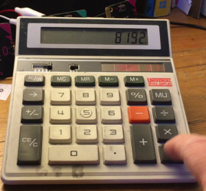
old desk calculatorLaura and Martin’s book is full of fun games and even a meme generator, but I wanted to make something a bit more prosaic: a calculator app. I wasn’t kidding myself this would be easy: as I discovered when I turned 3 micro:bits into a calculator, calculator UX and UI is surprisingly hard.

My aim was to use the simplest possible Python code, so anyone relatively new to the language could follow it. I also decided not to look at any other calculator and that it should behave pretty much like my ancient solar-powered desk calculator that I retrieved from a dustbin where one of my BBC bosses had thrown it because he disagreed with an answer it had given. To be fair, he had a degree in maths from Cambridge, so he was probably right.

Breaking down the code

I think real, practical projects are a great way to learn, so let’s break it down, chunk by chunk. There are probably more efficient ways of writing the code, this is just what I came up with today. Tomorrow I might write it very differently!

Here is every bit of code in order with some explanations. Note I always use single quotes at they are easier for children to type. You can find the full program here: https://github.com/blogmywiki/guizero-calc

Set-up

# imports -------------------------------
from guizero import App, Text, PushButton

# initialise variables ------------------
displayString = ''
a = False
b = False
result = 0
operator = ''
operatorFlag = False

Here I import the features of guizero that I’m using and initialise the variables. It stores the current displayed number in a string called displayString. a and b are the two numbers you’ll be adding, subtracting etc. result is the answer, operator is the operation you’ll be performing and operatorFlag is used to keep track of whether or not you’ve pressed an operator key.

# app -----------------------------------
app = App(title='MyCalc', layout='grid')
app.bg = '#000000'

This defines the title of the app that appears in the very top of the window. Guizero has a simple mode that just stacks elements on top of each other, but we need to select the grid layout for our calculator as we want buttons in a grid. I’ve also made the background of the app black (#000000) to look a bit like an Apple calculator app.

The functions

# functions -----------------------------
def inputNumber(key):
    global displayString, operatorFlag
    if operatorFlag:
        displayString=''
        operatorFlag = False
    displayString = displayString + key
    display.value = displayString

The first of several functions is inputNumber(). When you click on a number button, the button passes a string like ’7′ to this function which adds the number to the display string and shows it in the display element. If you’ve just pressed an operator key like ‘+’ or ‘x’ it clears the display string ready for the next number.

def operatorKey(key):
    global a, operator, operatorFlag, displayString
    operator = key
    operatorFlag = True
    if not a:
        a = float(displayString)

If you press an operator key, like ‘+’ or ‘-’, the button passes it to this function which assigns it to the operator variable. It sets the flag to say that it’s been pressed and if the first number, a, doesn’t exist because it hasn’t been set, it assigns the current contents of the display as a floating point number to a

def evaluate():
    global a, b, result, operator, displayString
    if not a and not b:
        return
    elif a and not b:
        b = float(displayString)
    if operator == '+':
        result = a + b
    elif operator == '-':
        result = a - b
    elif operator == '/':
        result = a / b
    elif operator == 'x':
        result = a * b
    # stop decimal places appearing for whole numbers
    if result - int(result) == 0:
        result = int(result)
    displayString = str(result)
    display.value = displayString
    a = result

This is the biggy! Evaluate does the calculation.

First, it checks that you have entered two numbers, a and and b.

If you’ve not set either number, it just bails out of the function with the ‘return’ instruction. This could be summarised as ‘come back when you’ve entered some numbers!’

If you’ve set a but not b, it then assigns the current display contents to b.

Then it gets on and performs the relevant calculation of your two numbers, checking that if the floating point result is actually a whole number. If it is, it turns it to an integer variable type to avoid trailing decimal points and zeros being displayed.

It then does one last thing: it assigns the result to the a variable, ready to be calculated on again. This means that, just like on a real calculator, if you press 7 + 2 = you’ll see 9, then if you keep pressing =, 11, 13, 15 etc.

def allClear():
    global a, b, operator, result, displayString
    a = 0
    b = 0
    operator = ''
    result = 0
    displayString = ''
    display.value = '0'

This function allClear() is called if you press the AC (all clear) button. It resets everything back to 0.

def backspace():
    global displayString
    if len(displayString) > 1:
        displayString = displayString[:-1]
        display.value = displayString
    else:
        displayString = ''
        display.value = '0'

Rather than having a CE (clear entry) button I decided to implement a backspace instead. It trims the last character of the display string, unless it’s shorter than 2 characters long, in which case it just clears it.

Layout and buttons

# layout & buttons ----------------------
display = Text(app, text='0', color='#FFFFFF', grid=[1,0,15,1])
display.text_size = 37

display is the area in which the numbers are displayed. I set the initial text to ’0′ and the text colour to white. You can specify fonts, but I decided to leave it to a default font and it looks ok on a Mac at least. The grid statement puts it in the second column with a stupidly large span of 15 columns and 1 row to prevent it moving the buttons too much when the numbers get long. This needs a bit of work as if you divide 22 by 7 the buttons do still spread out a bit.

btn7 = PushButton(app, command=inputNumber, args=['7'], text='7', grid=[0,1])
btn8 = PushButton(app, command=inputNumber, args=['8'], text='8', grid=[1,1])
btn9 = PushButton(app, command=inputNumber, args=['9'], text='9', grid=[2,1])
btn4 = PushButton(app, command=inputNumber, args=['4'], text='4', grid=[0,2])
btn5 = PushButton(app, command=inputNumber, args=['5'], text='5', grid=[1,2])
btn6 = PushButton(app, command=inputNumber, args=['6'], text='6', grid=[2,2])
btn1 = PushButton(app, command=inputNumber, args=['1'], text='1', grid=[0,3])
btn2 = PushButton(app, command=inputNumber, args=['2'], text='2', grid=[1,3])
btn3 = PushButton(app, command=inputNumber, args=['3'], text='3', grid=[2,3])
btn0 = PushButton(app, command=inputNumber, args=['0'], text='0', grid=[1,4])
btnDec = PushButton(app, command=inputNumber, args=['.'], text=' .', grid=[2,4])

btnDiv = PushButton(app, command=operatorKey, args=['/'], text='÷', grid=[3,1])
btnMult = PushButton(app, command=operatorKey, args=['x'], text='x', grid=[3,2])
btnSub = PushButton(app, command=operatorKey, args=['-'], text='-', grid=[3,3])
btnAdd = PushButton(app, command=operatorKey, args=['+'], text='+', grid=[3,4])

btnEquals = PushButton(app, command=evaluate, text='=', grid=[4,4])
btnAC = PushButton(app, command=allClear, text='AC', grid=[4,1])
btnCE = PushButton(app, command=backspace, text='←', grid=[4,2])

All the buttons in a grid! I didn’t try to change their colours because, well, on a Mac you can’t. Buttons should be grey anyway, right?

The grid numbers specify the column and row of each button, staring at 0 as the first column.

You can specify a function to call when you push a button using command=...

If the function takes parameters, like inputNumber or operatorKey, you have to use args=[] to pass it. If you used, say operatorKey(7) instead, the function would fire as soon as you open the app and put a number 7 on the display before you’d even clicked on anything. (Thanks to Matt, Carlos & Laura for helping me figure that out!)

The sneaky infinite loop

# display app loop ------------------------------
app.display()

Finally, this line creates the app loop. It’s important to think of this as an infinite loop that keeps polling the keys for events. As they say in the guizero docs:

You may be used to writing programs which contain loops or make use of the sleep() command, but find when you try to use these with guizero they cause your GUI to freeze. This is because guizero (in common with almost all GUIs) operates an event driven model of programming which may be different to the one you are familiar with.

What did I learn?

- How to create an app with a simple grid of working buttons
- How to pass parameters to functions from inside a button
- Why some of my previous attempts at Python GUIs failed: they run in their own infinite loop and some basic, familiar programming methods don’t work in this strange, parallel, event-driven universe.

Posted in computers | Tagged , | 2 Comments

6502 breadboard computer: part 2

Having started to build a Ben Eater-style, 6502-based breadboard computer a few weeks ago, I’ve started to diverge my design a bit. Ben uses an Arduino Mega to monitor the status of the address and data bus, but I like old computers with blinkenlights and I also like the simplicity of a self-contained computer that doesn’t need an Arduino and another full-sized computer to display the data.

So I decided to keep the 16 LEDs I wired across the address bus, and added 8 new LEDs to the data bus, so I can monitor what’s going on, albeit in binary rather than in hexadecimal on an Arduino console screen.

Flashing an EEPROM

eeprom programmer

If we’re going to write a real program, instead of hard-wiring no operation instructions, we’ll need some sort of memory. The first kind we add is a read-only memory (ROM) so that the program remains when the power is off. This is used in old computers like the KIM-1 and Acorn System 1 to store the monitor program that allows you to enter code on a keypad and show things on an LED display. More complex systems like the Apple ][ and Commodore PET stored a BASIC interpreter in ROM as well as the machine's operating system.

As I want to keep changing the program as I develop the system, I need a kind of ROM that I can modify, which is where the EEPROM (electrically erasable programmable read-only memory) comes in.

It was quite exciting flashing my first ever EEPROM. Back in the day (by which I mean the 1970s) I think EPROMs had to be erased using ultraviolet light and the process took a very long time, but now you can erase and flash a 32K EEPROM in a few seconds. I got an inexpensive programmer from China, which comes with Windows software but, being on a Mac, I installed a command line utility called minipro, which I installed using brew at the MacOS terminal command line:

brew install minipro

I modified Ben Eater's first program to add a loop and some different values. It just loads hex value aa (binary 10101010) into the accumulator, writes that out to memory location 6000, does the same with hex 55 (binary 01010101), and then loops back to the start of the program.

I also modified Ben's short Python program (code below) to create a binary file of exactly the correct length (32k) to fit on the EEPROM, which fills all the empty spaces with NOP (no operation) instructions - ea in hex.

You'll see that memory addresses are given 'backwards', i.e. address 6000 is coded as 00 then 60. This is the way that the 6502 (and some other processors) encode 2-byte addresses. It seems odd, but apparently there's a potential speed gain to be had from doing it this way. It's called little-endian encoding, after the pointless wars in Jonathan Swift's Gulliver's Travels over which end of a boiled egg you should crack open first. And, having done some machine code programming of my own, I finally understand it! The smaller (littler) byte of the two bytes comes first.

The other thing to note here is the 8000 address stored right near the end of the ROM, at locations 7ffc and 7ffd. This is the reset vector, which is super-important. When the 6502 processor is reset, it looks at these memory locations for the address at which it will find its instructions, the program you want it to run. In this build, we connect the EEPROM so that its first byte is at memory location 8000.

rom = bytearray([0xea] * 32768)
rom[0] = 0xa9   #LDA aa
rom[1] = 0xaa
rom[2] = 0x8d   #STA 6000
rom[3] = 0×00
rom[4] = 0×60
rom[5] = 0xa9   #LDA 55
rom[6] = 0×55
rom[7] = 0x8d   #STA 6000
rom[8] = 0×00
rom[9] = 0×60
rom[10] = 0x4c  #JMP 8000
rom[11] = 0×00
rom[12] = 0×80
rom[0x7ffc] = 0×00
rom[0x7ffd] = 0×80

with open(“rom.bin”, “wb”) as out_file:
  out_file.write(rom)

I connected the EEPROM programmer's USB cable to my laptop and burned the binary file created with the Python script on to it using this command:

minipro -p AT28C256 -w rom.bin

Wiring the ROM chip

I used an Atmel AT28C256 32k EEPROM chip. This, I have to say, was an absolute pig to wire up - look how illogical the address bus pins are! Pin 7 is next to pin 12 which is next to pin 14.

atmel eeprom pinout

I'm grateful to Pete Lomas for explaining to me that this illogical layout is caused by trying to maintain compatibility with older EPROMs and ROMs: no-one ever thought they'd be bigger than 1K, and room had to be found for the extra address lines.

So, I connected the EEPROM's address pins 0-14 to address bus pins 0-14 on the 6502 CPU, pin 14 to GND and pin 28 to +5v.

CPU address bus pin 15 goes via an inverter made from a NAND gate to the EEPROM’s CE (chip enable) pin 20. See Ben Eater's video for details. This is to ensure that the EEPROM is only enabled when the CPU is trying to address memory above location 8000.

Pin 27 WE (write enable) is tied high to +5v to prevent it being overwritten.

Pin 22 OE (output enable) is tied low (GND) as we want some output from the ROM.

The EEPROM I/O pins 0-7 are connected to data bus pin 0-7 on the CPU.

Running the program

first instruction annotated

So, I powered it all up. As you'll see from the video at the top of the page, I wasn't sure if it was doing the right thing at first, but when I reset the CPU and single-stepped through the program, I discovered it was working perfectly. The picture above shows its status at address 8000, the first instruction of the program in my EEPROM. The data bus is showing binary 10101001, which is hex 89. 89 is the opcode for the 6502 LDA instruction, which is the first instruction!

I stepped through the whole program and confirmed every LED on the data bus is showing either the instruction opcode, or data being read or written.first program byte by byte

The next steps will be to add the 6522 versatile interface adaptor (VIA) and a display. Ben Eater makes some LEDs blink next, but I feel I have enough blinkenlights, I may skip that and go straight to adding an LCD display driven from the VIA chip.

Eventually I'm going to want to add a keypad. I found a few articles about adding PS/2 keyboards, but I want something simpler and more KIM-1 like. I have some flexible 4x4 matrix keypads, which will do for entering hexadecimal numbers, but I'll need at least 4 more buttons I think to create a self-contained single-board computer: stop, go, up and down. If anyone has any advice about how to attach a small (say 4x5 or 5x5) keypad to a 6502, I'd love to hear it!

Read what happened next with my 6502 computer in Part 3...

Posted in computers | Tagged , , | Leave a comment