Drive 4 digit 7-segment LED displays direct from a micro:bit

I bought a bag of random 7-segment LED displays to play around with, originally with the idea of adding them to the address and data busses on my 6502 breadboard computer. That became a bit tricky, but I got thinking about adding them to a BBC micro:bit. You can buy excellent displays for the micro:bit, like this one from Monk Makes, but I decided to to build and code my own from scratch, and like building and coding my own keypads, I learned a lot about an electronic component we take for granted.

It turns out that single-digit displays work pretty much as I expected. Each segment has a pin, and you send some volts to the pins and they light up, so a display that shows one digit and a decimal point will have nine pins, one for each segment and a common anode or cathode.

Multi-digit displays work rather differently, however. A 4 digit display does not use 4 x 8 pins. Instead it uses the same 8 pins to choose which segments to light plus 4 extra pins to chose which digit is going to light up at any given time. This means you have to multiplex the display: set the pins for the first digit, light it up by selecting it, change the segments and select the second digit, and so on. So each number is flashed on in turn. The video at the top of the page shows it working slowly. Normally you flash the digits so quickly, persistence of vision means that to the human eye it looks like they’re all on at the same time. This article on Raspi.TV explains it really well.

My display is a common cathode type. This means that you have to ground each digit selection pin in turn to make that digit light up.

If you want to try this, as well as the 4 digit LED display you’ll need a micro:bit, a breakout board, a breadboard, some jumper wires and around 7 or 8 resistors. I used 330 ohm resistors, but you may be able to use lower values depending on your display. I didn’t wire up the decimal point, just the 7 segments. I connected them like this:

micro:bit pin   Resistor?   LED pin
--------------------------------------------------
0               yes         1
1               yes         2
8               yes         4
9               yes         7
12              yes         11
2		yes         10
13              yes         5
14              no          Digit 1 select (pin 12)
15              no          Digit 2 select (pin 9)
16              no          Digit 3 select (pin 8)
10              no          Digit 4 select (pin 6)

I decided to write the program to drive the display using MakeCode blocks. You can see the project here: https://makecode.microbit.org/_HxbLuUWob6Rs

It’s a simple counter that goes up and down when you press button B or button A. A forever loop keeps scanning the display, grounding each digit pin in turn to show the correct number. Timing is pretty crucial here, so I put the main program loop inside a ‘while true’ block inside the ‘forever’ block to remove the small delay that MakeCode adds to forever loops. It seems to work! I did occasionally see some ghosting artefacts, though I think it’s pretty amazing it works at all.

So, next time you look at a numerical LED display on a clock, cooker, or fridge, spare a thought for the design effort that went in to making it work.

Posted in computers | Tagged , , | 1 Comment

6502 breadboard computer part 8 – next steps

6502 breadboard computer

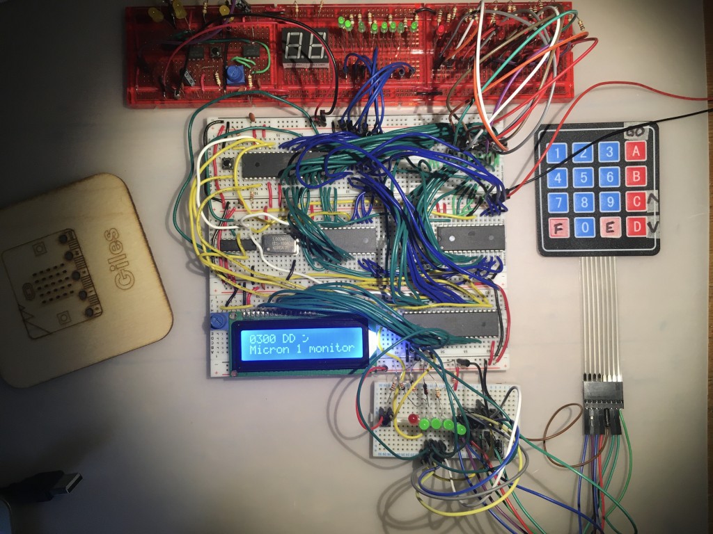
I recently achieved my goal of making a 1970s-style 6502 breadboard computer that I can use to practice machine code programming. It has a hexadecimal keypad for entering instructions, a 16×2 alphanumeric LCD display and a very basic monitor program that allows me to enter programs up to 256 bytes in length and run them.

So it’s time to take stock and consider what next…

Practice my coding
There’s a lot I can do with this computer to learn more about 6502 machine code. There are stacks of books and websites to mine, from classics like Programming the 6502 by Rodnay Zaks, to helpful blogs like this one and this interactive one.

Improve the monitor
- The Apple 1 computer had an amazingly compact monitor program written by Steve Wozniak, usually called ‘wozmon’ – the source code is available and it’ll be instructional to dig into it and see how it works. Straight away, for example, I saw he’d used logical shifts instead of rotates – if I’d done that I’d never have had the carry bug that was corrupting my display of hexadecimal numbers.
- I could also make improvements to the ROM to make displaying text easier. At the moment you have to load the ASCII value of the character you want to show into the accumulator and call a subroutine. There’s almost certainly a better way of doing this. I could make it easier to write text across two lines, for example.
- I don’t want a full assembler or typewrite keyboard, but I do have a lot of spare shift-keys, so it might be fun to put frequently used opcodes as shortcuts on some spare keys, Sinclair ZX81/Spectrum-style.
- It might be useful to use the second line of the monitor display to show the contents of key registers and status flags.
- Add some way of making it easier to include keypad input in user-entered programs. This needs some thought and maybe a fundamental redesign of my monitor. At the moment the monitor sits in the ROM and pressing a key triggers an IRQ which updates the monitor display. Pressing GO (shift-A) jumps to memory location $0300 and starts executing any user-entered program. You can drop out of the user-entered program and back to the monitor with an RTI instruction. I guess looking at wozmon or even the Kim-1 monitor program might be instructive.
- Allow longer programs perhaps, but will I ever really want to type more than 256 opcodes by hand? (See note below on adding, or not adding, storage).

You know nothing of future time, and yet in my teeming circuitry I can navigate the infinite delta streams of future possibility and see that there must one day come a computer whose merest operational parameters I am not worthy to calculate, but which it will be my destiny eventually to design.
The Deep Thought computer in The Hitch-Hiker’s Guide to the Galaxy by Douglas Adams, Series 1, Fit the Fourth.

Improve the hardware
I could rewire the LCD and redesign the monitor code to drive it in 4-bit mode to free up 4 more I/O pins on the VIA, but I’m not sure what I’d actually use them for. I think I’m going to keep this machine pretty much as it is, so no video output, no storage device, no serial access, no BASIC interpreter… but perhaps design and build a second machine. This will have a full keyboard, BASIC and rather than a video output, a wide LCD display and maybe even a thermal printer in an Aim-65 style. I’d decided this and then discovered this amazing project, which is very close to what I want to build.

I’m keen to keep it broadly sympathetic to 70s/80s tech, so I’d like to avoid any microcontrollers that are more powerful than the 6502 itself… but what do you think I should do next?

Posted in computers | Tagged , | 3 Comments

6502 breadboard computer part 7 – working monitor program!

I love it when things work! Ok, it wasn’t entirely plain sailing, but progress on this has been rapid in the last few months.

A quick recap:

  • As a child in the 1970s I wanted my own self-contained single-board computer like a Kim-1 or an Acorn System 1. I couldn’t afford one then, though I have to say the latter especially would have been a sound investment, dad, but I guess I’d better let that go.
  • Machines like these have simple LED displays and you usually program them with raw machine code opcode hexadecimal numbers.
  • Ben Eater’s guides to making a 6502 breadboard computer have helped me realise that dream, despite not having an oscilloscope or logic probe, little knowledge of electronics and a distant memory of 6502 assembler from my big brother’s Kim-1.
  • I caught up with Ben to the point where he’s started looking at full keyboards, and as I don’t want that, I only want a hex keypad and a few buttons, I designed my own keypad interface using an encoder chip and a shift key (see earlier posts).

I’ve now written my own, very basic monitor program, and it seems to work. I’m pleased with its elegant simplicity.

  • Type hex numbers on the keypad and they get loaded straight into the current memory location.
  • Browse backwards and forwards in memory with shift-C and shift-D.
  • As well as the current address and memory contents, the display also shows an ASCII representation of the memory contents, useful if displaying text.
  • Run a program by pressing shift-A.
  • Stop it by pressing the CPU reset button, which drops you back into the monitor at $0300.
  • Programs can only be 256 bytes long. I may change this but, frankly, I can’t see myself typing in any program longer than 256 bytes.
  • User-entered programs always start at $0300 and always run from $0300 when you press shift-A. I may change this so they run from the current location instead, which would allow you to enter and test multiple small programs.
  • The user can access ROM routines to display text ($80D7) and send control codes ($80C0) to the LCD display. These addresses, of course, may change if you modify the ROM in any way.
  • There’s no easy way to scan the keypad in your user-entered programs yet – that’s something for me to work on.

Here are my first programs I entered and ran. The first just clears the LCD display and sits in a loop doing nothing.

address	mnemonic		op code		description
-------------------------------------------------------------
$0300	LDA $01			A9 01		Clear screen
$0302	JSR [lcd instruction]	20 C0 80
$0305	JMP [here]		4C 05 03        Infinite loop

The next one clears the screen and prints the ‘h’ of ‘hello world’.

address	mnemonic		op code		description
-------------------------------------------------------------
$0300	LDA $01			A9 01		Clear screen
$0302	JSR [lcd instruction]	20 C0 80
$0305	LDA “h”			A9 68           print 'h'
$0307	JSR [print_char]	20 D6 80
$030A	JMP [here]		4C 0A 03	Infinite loop

Here’s another program. Add two numbers, store the result in memory just after the program at $0309. As luck has it, RTI (return from interrupt) drops you back into the monitor so you can start examining your results as stored in memory.

address  mnemonic     hex        notes
--------------------------------------------------------
$0300    CLC          18         clear carry
$0301    LDA #$40     A9 40      load $40 into A
$0303    ADC #$02     69 02      add $2
$0305    STA $0309    8D 09 03   store result at $0309
$0308    RTI          40         jump back to monitor

It’s been a hugely educational experience. I’ve gained huge respect for hardware designers – frankly I think it’s amazing any calculator works let alone a phone or computer. I’ve learned precisely why pull-down or pull-up resistors are needed, by seeing first hand at a logic level what happens when you don’t use them. And I’ve also rediscovered the joy of assembler. It’s really not that hard as you have incredibly few instructions to play with. Every problem truly needs decomposing like you wouldn’t believe.


Source code: https://github.com/blogmywiki/6502

Posts in this series
Part 6
Part 5
Part 4
Part 3
Part 2
Part 1

Posted in computers | Tagged , | Leave a comment

6502 breadboard computer – part 6 – shift key

Last time I added a 4×4 keypad to my 6502 breadboard computer so I can enter opcodes as hexadecimal numbers, but I was worried that I needed more keys and didn’t have enough I/O pins left.

To make a self-contained computer like a Kim-1 or an Acorn System 1, you need to be able to enter not just opcodes for instructions, you need function keys as well to step forwards and backwards through the program you enter, start it running and stop it.

I found that I did have one single I/O pin left on the VIA (versatile interface adaptor) chip – PA4. It is possible to daisy chain another 4×4 keypad using some logic, but I don’t need 16 more keys (although you could make a full alphabet keyboard that way!). So I decided to make my own simple shift key.

I added a push button, and some code to read the status of PA4. The idea is that pressing unshifted keys caused them to display on the LCD, but if I press shift and D it will step forwards through memory, shift and C will step backwards. Baby steps, if you like, towards making a full monitor program.

Thinking this was just a simple matter of sending 5v up it when the button is pressed, I just wired it between PA4 and the 5v rail. And at first, it worked! Press keys – they displayed. Press shift D, it steps forward. But shift got stuck. I let go of the shift key but it carried on behaving as if shift was still pressed. Why?

You’re probably way ahead of me here, but it was a very useful learning point. I’d heard of pull-up and pull-down resistors in logic circuits before, I knew they were a thing, but only now did I understand at a very fundamental level why they may be needed.

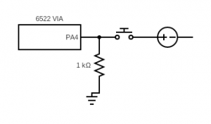
Pressing my shift button sent 5v up pin PA4 and changed its status from 0 to 1. But when I let go, what changes it back again? You literally need something to pull it back down to ground, 0v. Hence the need for a pull-down resistor:

diagram of a pull-down resistor

Pressing any key generated a signal on the DA (data available) pin which I use to trigger an IRQ (interrupt request) on the processor via the 6522 VIA chip. I modified my IRQ code like this.

irq:
  lda PORTA		; read contents of PORTA into memory
  sta inport
  lda inport		; read the state of PORTA back into A again - needed?
  and #%00001111	; strip out all but the key encoding
  sta inkey		; store the key value in memory
  lda inport		; read the state of PORTA back into A again
  and #%00010000	; read the shift key input
  beq no_shift		; if zero flag set, no shift key is pressed
  lda #$01		; if shift pressed, set shift flag
  sta shift
  jmp shift_cont	; skip clearing the shift flag, obvs
no_shift:
  lda #$00		; if shift not pressed, clear shift flag
  sta shift
  jmp update		; if no shift key is pressed just update the display
shift_cont:		; there was a colon missing here but it worked!
  lda #%00001111	; is the key 'd'?
  cmp inkey
  bne key_c		; if not, jump to next test
  iny			; if it is 'd', increment the location being displayed
key_c:
  lda #%00001101	; is it 'C'?
  cmp inkey
  bne update		; if not, skip decrementing
  dey			; if it is, decrement location index
update:
  jsr lcd_mon
  rti

So, some real progress. I can type hex numbers on the display and use a shift key to gain extra function keys when I need them. Next step is to enter and store real data or opcodes in memory using the keypad.


Source code: https://github.com/blogmywiki/6502

Posts in this series
Next – Part 7
Part 5
Part 4
Part 3
Part 2
Part 1

Posted in computers | Tagged , | 3 Comments

6502 breadboard computer – part 5 hex keypad

Having made a very simple proto-monitor work that allows me just to read the contents of memory on the LCD display, I decided to get a hex keypad working as a next step. Eventually I’ll use the hex keypad to enter machine code instructions I can run on the computer.

The video above shows it working and explains more, but here’s a quick explanation.

As I discovered with my micro:bit hex keypad projects, a 4×4 keypad needs at least 8 wires to connect it direct to a microcontroller. Because the LCD display is using 11 I/O pins on the 6522 VIA (versatile interface adaptor), I’m going to need some kind of encoding chip. Several other folk have used an obsolete chip called the 74C922. I got a couple off ebay for not much money. You connect it up to power, ground, a couple of different capacitors and all the rows and columns on your keypad. These membrane keypads are very inexpensive and even come with self-adhesive backs. Fablon-tastic! You press a key and it squirts data out on 5 pins.

The DA (data available) pin goes high whenever you press a key. Use this to trigger an interrupt request in your program to then figure out what button you pressed and what to do next.

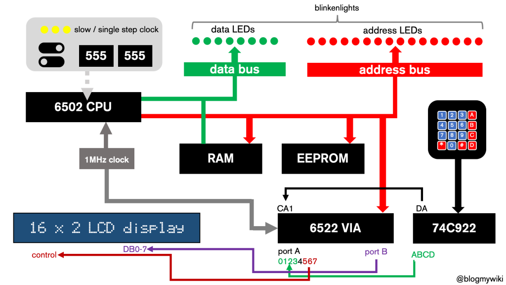
Here’s a very rough schematic of my Ben Eater-style computer with a bit more detail on the keypad:

breadboard computer schematic

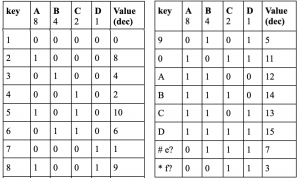
The 4 pins A-D send out 16 different patterns of signals, in effect a binary number encoded in a 4-bit nibble, each binary number representing a different key.

My test program literally just types the characters on the LCD display using a neat trick from another breadboard computer enthusiast Robin Harris. Robin’s taken a slightly different approach to Ben Eater to save pins, and his project is well worth a look. Having read this 4-bit value sent from the key encoder chip to port A on the VIA, you use this to offset or slice a string containing all the possible characters.

table of keycodes

Because of the way my keypad is wired up, I need to use the string ’174*396#2850ACBD’ rather than something more logical, but it works just fine and I thought it was easier to change one line of code than do lots of re-wiring.

Now this is great but it leaves me with a problem: to make a working computer I need at least 4 more keys, maybe more. I’ll need to be able to scroll backwards and forwards through memory, enter data, run the code and stop it so I can drop back into the monitor program without pulling the power and losing all my hard work typing the program in.

There are a few options here. I could re-wire and recode so that the LCD works in 4-bit mode. This would be a pig to program, but would free up 4 more precious I/O pins on the VIA. Or I could try and add a shift key or even another 4×4 keypad – the video shows how this is possible with the 74C922 encoder and a bit of logic. Both those last two solutions require one more free pin. In the video you’ll see me realise that I actually do have one spare, as I think PA4 is currently unused.

Watch this space!

Source code: https://github.com/blogmywiki/6502

Posts in this series
Part 6
Part 4
Part 3
Part 2
Part 1

Posted in computers | Tagged , | Leave a comment