How the micro:bit helps you understand fundamentals of computing

I’ve made a few projects recently using 4 x 4 membrane keypads with the BBC micro:bit. I made a calculator, then a wireless communicator and most recently I recreated the 1970s game Mastermind.

I thought it might be interesting to focus on how keypads (and by extension, computer keyboards) work and unpack some more of the learning around this. I think this shows how good the BBC micro:bit is understanding how technology works at a very fundamental level, but at the same time being quite simple and accessible, using block coding thanks to Microsoft MakeCode, and simple components thanks to the design of the micro:bit itself.

There are, for example, many Arduino projects for wiring up keypads but they are difficult to program, using C++ in the Arduino IDE which isn’t very child friendly, and yet at the same time using provided Arduino libraries actually shields you from learning what’s going on at a fundamental level.

Here we’ll see how the micro:bit gives you the best of both worlds: a simple, friendly online code editor, and yet you’ll write your own program to scan and interpret keypresses.

While I was waiting for my ready-made keypads to arrive, curiosity got the better of me. I had a breadboard and a bag of around 100 tiny push-buttons and decided to see if I could make my own. I knew keypads were arranged in a grid or matrix, but I was curious to know exactly how they were wired together.

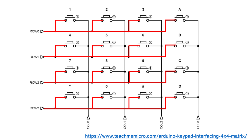
Looking at a circuit diagram of a keypad you can see that the same side of each button, the left side here, is connected together, row-by-row:

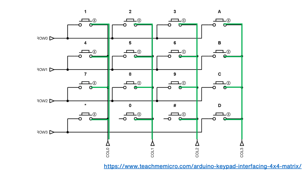
In each column the other side of each switch is connected together:

keyboard matrix wiring diagram columns

This gives you 8 wires for a 4 x 4 keypad. That sounds like a lot, but if you connected each key separately to a computer, calculator or microcontroller you’d have 16 wires plus a ground or earth wire connected to each button as well.

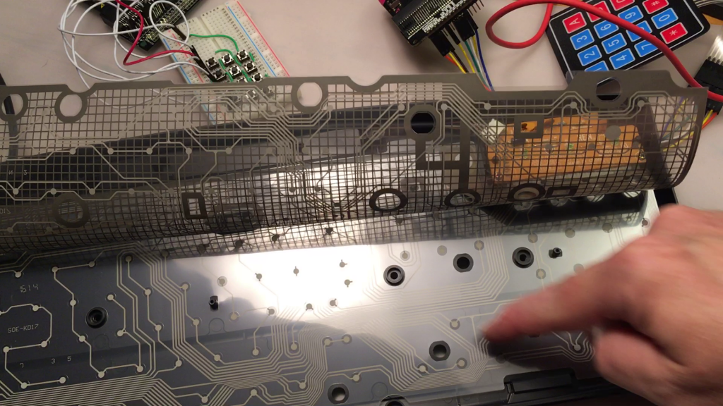
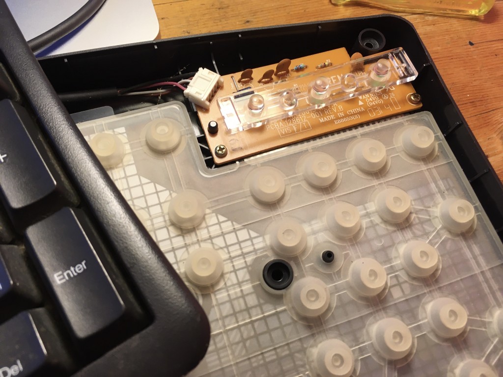
matrix inside a computer keyboard

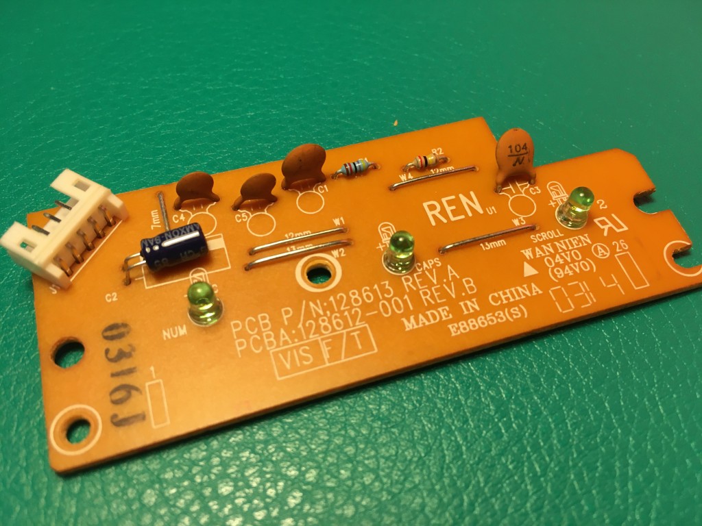
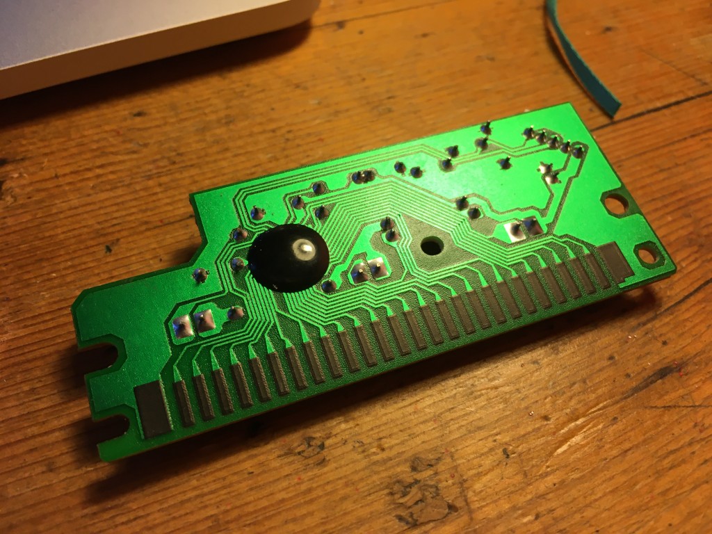
Inside a computer keyboard

A standard computer keyboard contains around a hundred keys, so inside a keyboard these are usually arranged in a matrix as well, perhaps 6 rows of around 15 keys, meaning it needs just over 20 wires, rather than a hundred.

So a matrix is really a very neat way of arranging keyboard inputs on electronic devices.

micro:bit connected to a home-made keypad matrix

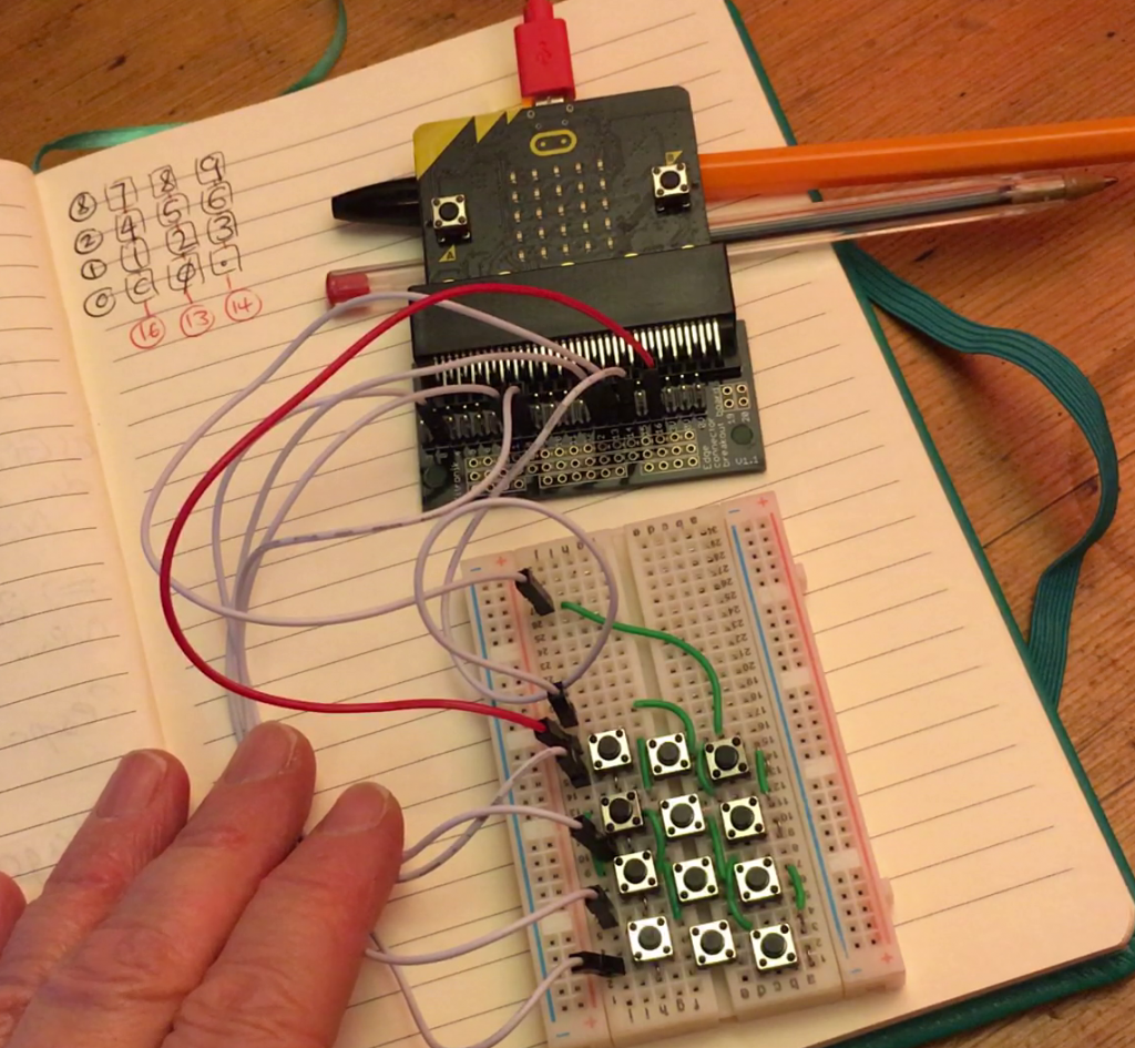
Making my own was fun and quite therapeutic! As every column in a breadboard is connected, and I only wanted to connect one side of each column of buttons together, I decided to stagger the buttons across the board. I used jumper wires to make the connections on each row and column. What you can’t easily see is that there are also jumper wires running underneath each button as well.

So, electrically speaking at least, I had created something that was the same as a real keypad matrix, even if I only had 12 buttons not 16.

But how to make it work?

I didn’t realise at the time that there was already a MakeCode extension for matrix keypads, which was lucky really as I had to invent my own way.

I knew some projects used different values of resistors to read pins using fewer than 8 wires, but I wanted to do it using as few components as possible. Using a breakout board on a micro:bit gives you access to extra pins, and I picked the following pins for rows and columns:

I avoided some pins that are also connected to the micro:bit’s own A and B buttons and elements of the LED display, as I want to able to use them in my projects.

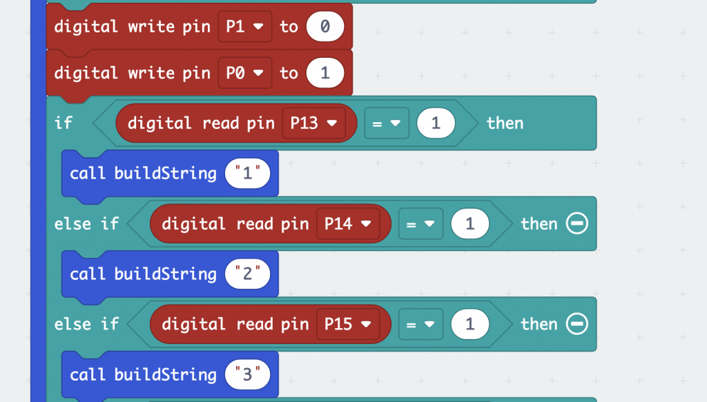
Using digital outputs and inputs on micro:bit pins is a simple way of detecting if a circuit has been made, so I created a loop in MakeCode that sends a digital output to each row in turn:

MakeCode blocks to scan one row

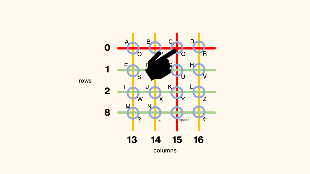
If it receives an input on any of the pins connected to the columns, then that means you must have pressed a button and the program responds accordingly, for example by showing a number or letter. The example below shows how the number 3 in my calculator or Mastermind game, or the letters C or Q would be detected in my communicator project:

a keypress is detected

I really didn’t expect this to work – but it did! I didn’t even have to add any code to debounce… it just seems to work!

Whilst making your own keyboard matrix out of buttons is instructive, it is very fiddly and time-consuming, and you can still learn a lot from using a pre-made keypad matrix. All you need to connect one of these to a micro:bit is a breakout board and some male to female jumper wires.

The code is quite simple to understand, and modify to suit whatever project you happen to be making.

What other fundamentals of computing can you expose and teach with the mighty micro:bit?

Posted in microbit | Tagged , | Leave a comment

Mastermind game for micro:bit

Following my calculator and communicator projects, I decided to recreate the classing 70s game Mastermind on the micro:bit.

Mastermind was based on an older game, possibly called Bulls and Cows or Moo! There have been various computer versions of it over the years, and this is mine. It’s based on guessing numbers. Here’s how to play:

  • The micro:bit thinks up a random 4 digit number which you have to guess.
  • Each digit is unique and there are no zeros.
  • You type in your guess and press D.
  • The micro:bit tells you how many bulls you have – a bull is the right number in the right place. Then it tells you how many cows you have, a cow being a correct number in the wrong place. (Sorry about the sexist bovine terminology, but I can’t think of a better short word to explain it – if you can think of a better pair of names, I’d love to change it!).
  • Use deduction (and luck!) to improve your guesses and work out the secret number.
  • When you do guess it, the micro:bit tells you how many turns it took you.
  • If you give up, there is a cheat mode: press buttons A+B together.

The video explains more about how it works but it’s worth calling out two bits of code that I think are moderately neat.

unique number generation code blocks

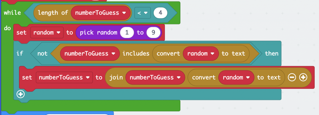
These blocks create a 4 digit random number string with unique digits. It uses a while loop which keeps executing until the string is 4 characters long. It picks a random number and if that number is not already in the string, it adds it. When the string reaches 4 characters in length the loop finishes.

counting bulls and cows code

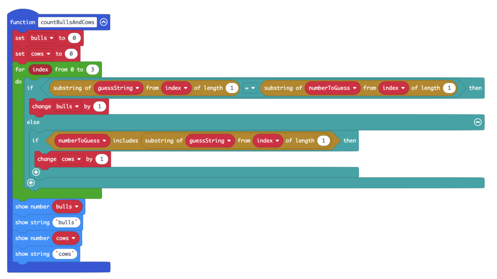
This function counts bulls and cows. It uses a for loop. The first character in a string is at position zero, so starting at 0 is fine. It compares each digit in position in your guess with the digit in the same position in the target number. If they match, that means it’s the right number in the right place, which is a bull, so we increase the bull counter by 1.

If it’s not a bull, then that digit may be a cow, so it then checks to see if the string contains that digit. We don’t need to worry that bulls will also be counted as cows as we’ve already excluded the bull in the first part of the if… statement.

The MakeCode project is below if you want to build your own or explore the code and perhaps improve it. See the communicator project for details of how to connect a 4×4 keypad to your micro:bit – you just need the keypad, 8 female to male jumper wires and a breakout board for the micro:bit.

Posted in microbit | Tagged , , | Leave a comment

micro:bit wireless keypad communicator

Learn how computers scan keyboards and make your own wireless texting machine!

Building on my micro:bit calculator project, which uses a 4×4 membrane keypad attached to a breakout board, I made a simple device so you can send and receive text messages over radio using micro:bits.

One of the problems of sending radio messages with a micro:bit is that it only has two buttons, so you have a few choices: encode the message in the code itself, which means you need a computer or mobile device to change the message; use a clunky user-interface to select each letter using lots of button pushes; or you can use Morse code.

Adding an inexpensive 4 x 4 membrane keypad makes messaging much simpler. 16 keys are not enough for the whole alphabet, but if we use a shift key we have 32 buttons, enough for the alphabet and some punctation. We’ll have to spell numbers out, and we can only have upper case letters (or lower case, but not both).

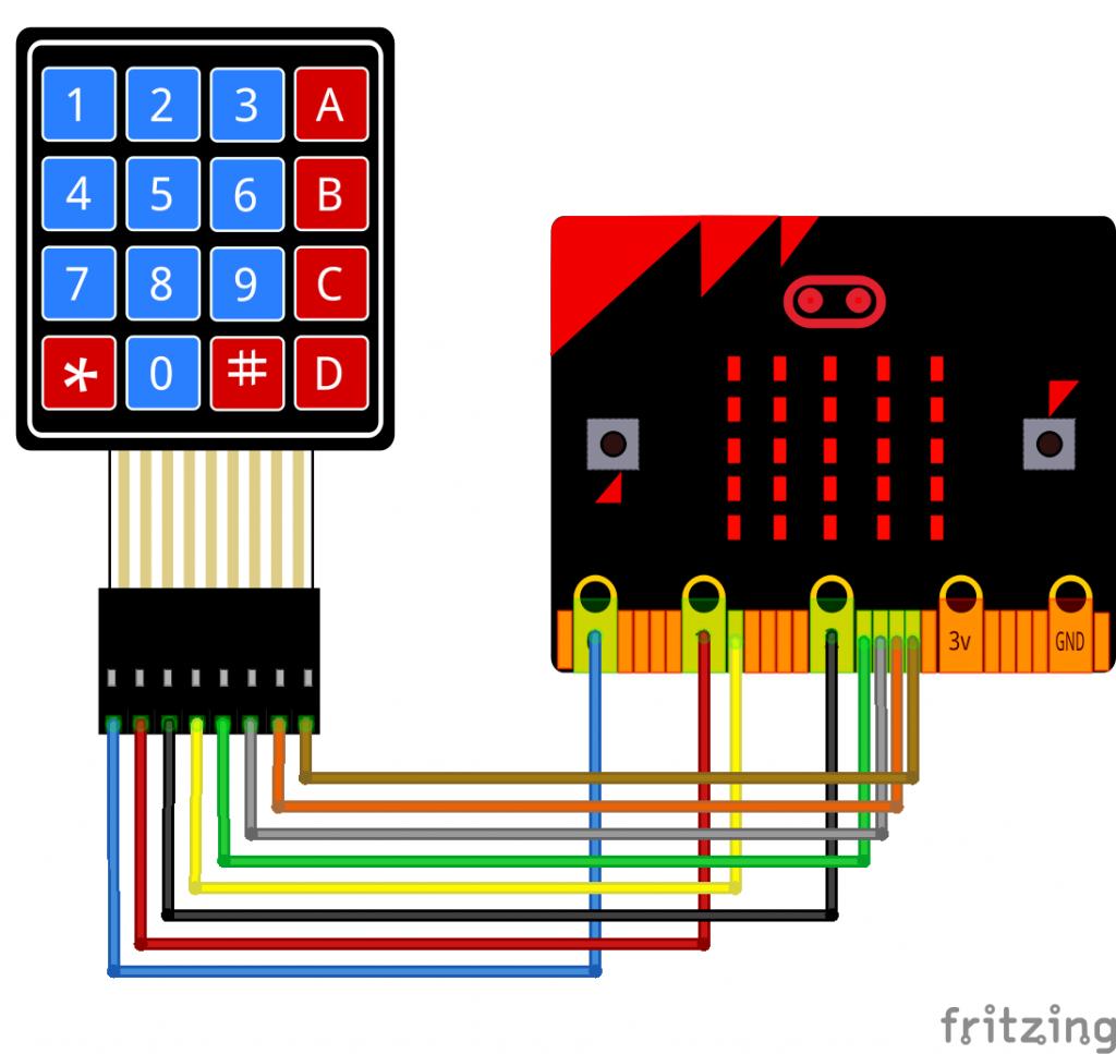
The keypad is attached to the micro:bit via breakout board and some female-make jumper leads like this:

4x4 keypad wiring diagram

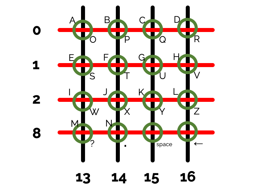
The keypad’s rows, its first 4 connections, are wired to micro:bit GPIO (general purpose input-output) pins 0, 1, 2 and 8. I skipped some pins because some are also used for the display and A and B buttons.

The keypad columns are wired to micro:bit pins 13, 14, 15, 16.

4x4 matrix wiring diagram

It works by sending out a digital ’1′ signal on each of the row output pins in turn and then reading the inputs from the column pins.

When you press one of the buttons, you complete the circuit and the signal comes back and can be read on the digital input column pins. This is how pocket calculator, and even computer keyboards work: they don’t have a wire connected to every button, instead they arrange keys in a grid (or matrix) like this, which they read by scanning rows and columns just like we do here. If you watch the program running in the MakeCode simulator you may also be able to see the scanning happenning.

Button A on the micro:bit acts as the shift key to swap between letters. I re-labelled the keypad with some masking tape and a Sharpie so I know which button to press, but in case I make a mistake there’s a backspace key and a space key that don’t require any use of shift, they always have the same function. (I could have used something like T9 multi-tap, but I think this is simpler – if you disagree, try coding your own T9-type text entry!)

Pressing button B transmits the message by radio to another micro:bit, on radio channel 23. It could be picked up by any other micro:bit MakeCode program, or by one running exactly the same code as this.

One thing to note is that the main forever loop has a small pause added. This is to allow time for the micro:bit to stop and process the on radio received block.

Let me know if you make one of these – the parts are not expensive, I bought a 5-pack of the keypads for well under £10. It could make a fun multi-player espionage game, perhaps adding some cryptography and code-breaking. Or you could just use it for socially-distanced messaging, as the range of the micro:bit’s radio is very much more than 2 metres!

.

Update: MakeCode extension

I’ve just discovered from @liou_jj in Taiwan that there’s a MakeCode blocks extension for these kinds of keypads: https://github.com/lioujj/pxt-keypad. I’ve not tried it, but it does look useful as it lets you set your own pin numbers so you can use it with other peripherals or avoid the pins used for buttons A and B or the display. I’d still recommend checking out my code above because it allows you to learn how keyboard scanning works, but an extension like this could make it easier to add keypads to your projects.

Posted in computers, microbit | Tagged , | Leave a comment

micro:bit calculator with external keypad

I learned a lot about how matrix keyboards work in a recent micro:bit project where I made my own out of some buttons and wire.

It’s much simpler, though, to use a ready made one and these 4×4 membrane keyboards were very inexpensive as a 5-pack. I set about wiring them up to a micro:bit and creating a simple calculator program in Microsoft MakeCode.

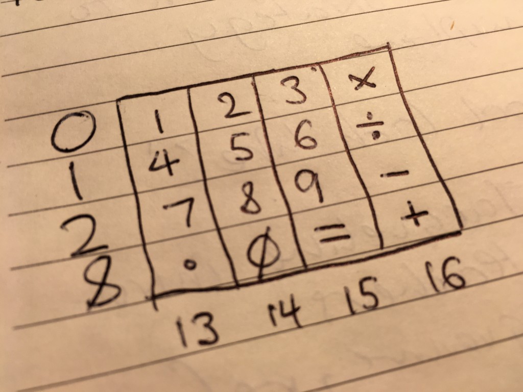
keypad wiring and layout

The keypad layout is not the same as a normal calculator, which has 7 8 9 in the top row, but it’ll do. I used the A B C D keys for the operators multiply, divide, subtract and add. I used the * button as decimal point and # as the equals key.

The first 4 pins on the keypad are the matrix rows, I connected them to micro:bit pins 0, 1, 2 and 8. (I skipped some pins which are also used for the display.)

The next 4 pins are the columns and I connected them to micro:bit pins 13, 14, 15 and 16.

4x4 keypad wiring diagram

If you have male-female jumper wires you don’t even need a breadboard to connect the keypad to your micro:bit, but you will need a micro:bit breakout board to access the pins.

To use the program, flash it on to a micro:bit. It will only add, multiply, divide or subtract two numbers. Each button press flashes the number on the screen, so pressing 2 2 will enter the number 22.

The program stores this as a text string, and when you press an operator key it assigns the number to variable a (also a text string).

When you press equals, it assigns the second number to variable b and then the calculate function converts the a and b strings to numbers using the parse to number block and carries out the appropriate calculation. If you miss the answer scrolling across the screen, you can press equals again to see it. Press button A on the micro:bit to clear, and button B shows you the currently stored calculation without actually giving the answer.

Here’s the code – it’s quite long but uses functions to try and make it more readable. The longest function is scanKeys which sends a digital signal out on each row in turn and reads the column pins to see if a connection has been made. I really didn’t expect this to work, but it seems to and doesn’t even require any de-bouncing.

Can you think of any other uses for a 4×4 keypad on a micro:bit? Some ideas floating round my head:
- noughts and crosses game
- Simon memory game
- controlling a robot
- making a micro:bit version of an early computer like a Kim-1 or an Acorn System 1
- electronic door lock
- alphabetical character entry using shift keys or 2 micro:bits and keypads for a radio / cryptography messaging project

.

Update: MakeCode extension

I’ve just discovered from @liou_jj in Taiwan that there’s a MakeCode blocks extension for these kinds of keypads: https://github.com/lioujj/pxt-keypad. I’ve not tried it, but it does look useful as it lets you set your own pin numbers so you can use it with other peripherals or avoid the pins used for buttons A and B or the display. I’d still recommend checking out my code above because it allows you to learn how keyboard scanning works, but an extension like this could make it easier to add keypads to your projects.

Text communicator

If you like this project, try my wireless text message communicator next!
micro:bit text communicator

Posted in computers, microbit | Tagged , | 2 Comments

Learn how a keypad matrix works with a micro:bit

Use a micro:bit, some buttons, and wires to learn how a keyboard matrix works

Back in 2018 I had a go at making a simple pocket calculator using some micro:bits, and one thing that’s been bugging me ever since was the idea of connecting a numeric keypad to a micro:bit. Having not just 1 or 2 extra buttons, but 10, 12 or even 16 could make a micro:bit calculator much easier to use and much more like the real thing.

The BBC micro:bit only has 3 main GPIO (general purpose input-output) pins for connecting to the outside world, and that’s probably not going to be enough. If you use a breakout connector, however, you can access a whole load more.

There are some cunning projects that use resistors of different values to reduce the number of pins needed to read lots of button pushes. If you wire them together but with different resistors, you can measure an analogue input and work out which button was pressed.

Wiring it up

I took a different approach, though, deciding instead to use a pure matrix of keys. Although you can buy cheap matrix keypads, I happened to have a large bag of small push-buttons, so I decided to wire up my own matrix using a breadboard and some wire. Normal calculators and computer keyboards use matrices to reduce the amount of wiring needed to connect physical buttons to computational systems, and so in doing this I learnt a bit about how they work at a fundamental level.

micro:bit connected to a home-made keypad matrix

Wiring up the keypad was fun and quite therapeutic as a little break between Zoom calls. You can’t see in the picture but there are lots of tiny jumper wires underneath the buttons as well as the longer green wires. The buttons are staggered on the breadboard to make sure I only make electrical connections where I want.

The left leg of each button is wired together in a column. I then wired together the right leg of each button in rows. Now this looks like a lot of pins are needed, but imagine if you wired up each button separately, you’d need 12 pins for a 4×3 arrangement of buttons. Using a scanned matrix means you only need 7 pins, one for each row and column:

keypad wiring diagram

You can see circuit diagram of a 4×4 matrix here to get a better idea of the kind of wiring needed.

You have to be a bit careful which micro:bit pins you choose as some are used for other things like the display. I only need digital pins, however, as my keyboard scanner is going to send a digital signal output down each row in turn and then scan using a digital input every column in that row to see if any of the keys are pressed, completing the circuit and allowing the digital signal to pass.

I picked pins 0, 1, 2 and 8 for my rows and 16, 13 and 14 for the columns. Pins 13 and 14 are also used for an SPI interface, but I’m not using SPI here so I can just use them as GPIO pins. I’m probably also going to need a 4×4 matrix to add operator keys eventually, but for that I’m going to need a bigger breadboard and this started out as a proof of concept which I didn’t really expect to work.

How the code works

For my proof of concept, I wrote a simple MakeCode program (code at the foot of this post) to send a digital write signal out on each row in turn, and then if a signal is incoming on any column, put the relevant number of symbol on the display.

I connected it up, flashed the program – and it worked!

A few caveats: it’s slow. You have to hold each button down for quite a long time before it registers. This is partly because a MakeCode ‘forever’ block introduces a small delay into your program. You can get round that by putting a ‘while true’ block around everything inside the forever block, but one added bonus of the small delay is that you can see the scanning happen in the simulator:

The program could also be improved by using functions to scan the columns and there’s a lot of work to do to transfer this into a working program that uses keypresses to do anything useful like a calculator, but this was an interesting activity to learn how to make and program a keypad from scratch and learn some fundamentals of how software and hardware combine at quite a low level.

MakeCode blocks for keypad project

Posted in computers, hardware, microbit | Tagged , , | Leave a comment