6502 breadboard computer: part 1

The first computer I ever used, probably in 1977, was my older brother’s KIM-1. This was a bare, single board computer that was really just a development kit for the 6502 microprocessor. It just had 6 numeric LED displays and a hexadecimal calculator-style keypad with some extra buttons for entering, modifying, running and stopping programs running.

You programmed it in machine code – hexadecimal numbers that represented instructions and data. Although time-consuming and difficult, programming the ‘bare metal’ in this way is a great grounding in computer science and coding: it gives you an appreciation of how programs and hardware interact, but more fundamentally, it helps you learn how very much can be achieved with a very limited set of instructions. If you can add, you can subtract, you can multiply and divide, and so on.

The 6502 went on to power the Apple ][, Commodore PET, Commodore 64, Nintendo Entertainment System as well as the Acorn System 1 and the BBC Micro. I soon made the switch from machine code to BASIC, but always hankered after my own KIM-1 or Acorn System 1 - indeed I wish I'd nagged my parents more to but me the latter now, it would have been a pretty good investment. Acorn became ARM, and now almost every human on the planet has one of their microprocessor designs in their pocket. The other thing that stuck with me, coding in BASIC on a PET or ZX Spectrum, was the blinding speed at which machine code routines ran, whether utilities to flip graphics slideshows or entire games.

I previously explored turning a BBC micro:bit into a simple CPU-like machine, but thought for my winter project I'd have a go at building my own breadboard computer, based on the modern version of the 6502, the Western Design Centre W65C02S.

There's quite a vogue for building simple breadboard computers from the ground up, and I can of course recommend Ben Eater's video guides, which I'm using as the basis for my project. I'll be diverging a bit from his path, and I thought it might be worth documenting some of the problems I had along the way. I also highly recommend this single video from Wifi Sheep, who only takes the very first steps but explains everything very well for the non-expert.

Goals

  • To learn a bit more about the electronics associated with computer hardware design
  • To learn some electronics, full stop
  • To re-learn some assembly language for the first time in 40 years
  • Maybe eventually to make something with a simple display, keyboard and monitor program that can be programmed like a KIM-1 or Acorn System 1

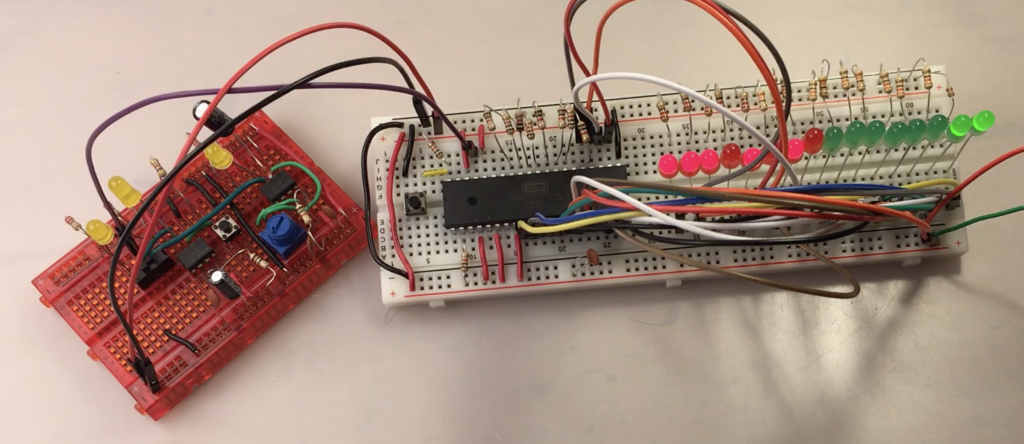
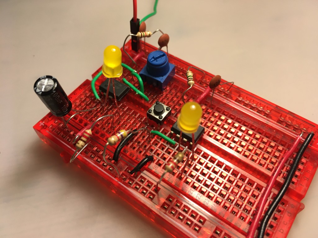
clock module

Starting with a clock

Making a clock seemed like a good place to start. I found Ben Eater’s clock a bit too advanced for my liking, and had originally intended just to have the option either to single-step the processor using a debounced button, or run it at the full 1MHz clock speed using a self-contained crystal oscillator IC.

In the end, I compromised a bit and built a clock using just two 555 timers which I can switch between single-step mode (using the 555 timer for debouncing) and a slow but variable mode which allows you to adjust the clock speed with a variable resistor. It’s basically the first two parts of the Ben Eater clock project, but I didn’t add the extra circuits to combine the logic, and I just added a simple single-pole / dual-throw switch to select which one I want to use. It’s not perfect, but it’s much simpler and more compact that Ben Eater’s, and I still learned a bit about 555 timers, and basic electronics with resistors and capacitors along the way.

Blinking lights!

It was now time to bite the bullet and connect up my modern 6502 processor. I ordered most of the bits Ben Eater uses from Mouser Electronics, and some other bits like the wire, LCD display and the EEPROM programmer from various suppliers in China. I guessed a bit, and time will tell whether I actually bought the right chips, I really didn’t have much clue what I was doing!

So, first step was to get some power to the processor, connect some LEDs across the address bus to see if it was alive and if my clock module worked. At first, I couldn’t get anything working at all. It turned out all the anti-static, anti-moisture packaging with its dire warnings had made me over-cautious. I just hadn’t pressed the pins of the CPU chip hard enough into the breadboard and they weren’t making contact.

first steps with the breadboard computer

I connected the pins of the W65C02 CPU like this:

w65c02s pinout

pin function notes
21 VSS GND for logic
8 VDD Main +5v power in
40 RESB Reset. Needs to be high to run; connects to 5v rail via a 1K resistor; connect a push button to GND rail as well.
38 SOB High, tie direct to 5v rail (set overflow)
2 RDY High, tie to high (+5v) via 1k resistor
4 IRQB High, tie direct to 5v rail (interrupt request)
6 NMIB High, tie direct to 5v rail (non-maskable interrupt)
36 BE High, tie direct to 5v rail (bus enable) – not connected in Wifi Sheep video

I connected some LEDs across the first few pins of the address bus (pins 9-14), powered both the clock and the CPU breadboard off an old USB lead which I chopped one end off and plugged into an old iPhone charger, and sure enough the LEDs on the address bus blinked madly.

Ordered blinking lights that count

That was quite exciting, but all a bit chaotic and meaningless. Following Ben Eater and Wifi Sheep I then hard-wired a NOP (no operation) instruction to the data bus. This means that the processor has an an instruction to follow, albeit one that does nothing, but it does mean you can see it scanning the address bus in some kind of logical order, and if you single-step the clock you’ll see that each NOP instruction takes two clock cycles to execute. I also added 16 LEDs across the whole address bus so I could see the whole bus being scanned.

full address bus LEDs

You need eight 1k ohm resistors for this. The NOP instruction’s hexadecimal code is EA, which is 11101010 in binary. Starting with pin 26, I connected them like this via 1K resistors

Pin     Connection
26  D7  +5v (1)
27  D6  +5v (1)
28  D5  +5v (1)
29  D4  GND (0)
30  D3  +5v (1)
31  D2  GND (0)
32  D1  +5v (1)
33  D0  GND (0)

Now you can single-step the 6502 through its initialisation sequence, and watch it then settle down to start scanning memory from location EA – and of course, as the single NOP instruction has been hard-wired across its data bus, this is the only instruction it can ever see, so it keeps on counting. It’s quite therapeutic watching the LEDs counting in binary, but next I need to run some real code, which means using some kind of assembler program and programming and adding some memory in the form of an EEPROM… what could possibly go wrong!?

Posted in computers, hardware | Tagged , , , | 2 Comments

Printing text on an LCD display using switches

There’s a YouTuber called the 8-Bit Guy who’s made a fantastic project where he gets text on an LCD display just using switches instead of a micro-controller or computer. He made his (video below) in a nice box with chunky switches, and I thought I’d try and make one on a breadboard.

This was a mistake, but I did, just about, get it to work and it makes an interesting project to learn a bit about low level logic, binary maths, data representation and so on with some very simple and inexpensive parts. It’s a good gateway to building a more complex project like a breadboard computer, which I plan to do this winter and it will use a display just like this so it’s all good practice.

Building it

Here’s what I used:

  • a 2 x 16 alphanumeric LCD display (old-fashioned parallel type, not one with an SPI interface)
  • 9 tiny single-pole dual-throw switches
  • a push-button
  • a 0.1uF capacitor to debounce the push-button
  • a variable resistor
  • a 4.7k ohm resistor
  • a breadboard
  • jumper wires
  • a USB lead with one end stripped to provide 5v power

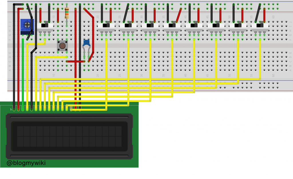
Here’s how I wired it up – I’d be very happy to be corrected on my inevitable mistakes – I am not an electronics expert in any way!

LCD switch wiring diagram

The LCD pin wiring goes like this from left to right:

LCD pin
 1 GND
 2 +5v
 3 variable resistor for contrast
 4 centre pole of register select switch
 5 GND
 6 one side of the enter button
 7 to centre pole of data switch
 8 to centre pole of data switch
 9 to centre pole of data switch
10 to centre pole of data switch
11 to centre pole of data switch
12 to centre pole of data switch
13 to centre pole of data switch
14 to centre pole of data switch
15 +5v for backlight
16 GND for backlight

Using it

Switch the program select switch to the 0v / GND position and enter some control codes. I tried a few different ones but found that this (sometimes) worked to select two line mode. Put the data switches in each position, then press the ‘enter’ button:

0000 1111
0011 0000

Then to enter text, switch the program select switch to the +5v position, alter the switches to the positions of binary representations of ASCII characters, and press the enter button after each one.

H 0100 1000
E 0100 0101
L 0100 1100
L 0100 1100
O 0100 1111
  0010 0000 (space)
W 0101 0111
O 0100 1111
R 0101 0010
L 0100 1100
D 0100 0100

The little breadboard switches are far too fiddly and prone to flying out of the board, so if I were to make this properly I would go the same way as the 8-Bit Guy and use big switches in a proper box.

If you fancy connecting one of these to a BBC micro:bit, check out my previous post: http://www.suppertime.co.uk/blogmywiki/2019/04/lcd-microbit/

Related videos

The 8-Bit Guy video that started me making this:

A Ben Eater video on adding LCDs to a breadboard computer which has very useful stuff on the control codes:

Posted in computers, hardware | Tagged | Leave a comment

micro:bit OLED compass

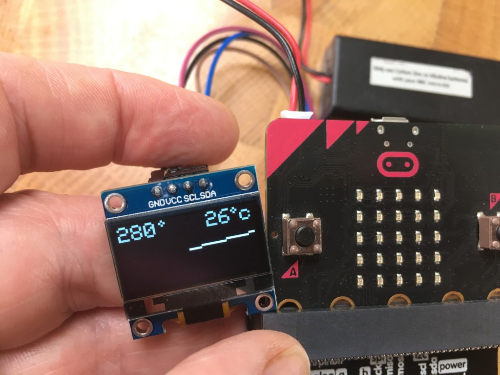
micro:bit OLED compass

These 128 x 64 pixel OLED displays are inexpensive and provide a great way to augment micro:bit projects. They’re easy to wire up using a breakout board and 4 female-to-female jumper wires. Just connect it like this:

OLED  / micro:bit
----------------
GND  -> GND
VCC  -> 3v
SCL  -> SCL (pin 19)
SDA  -> SDA (pin 20)

There are lots of different ways of driving OLED displays from a micro:bit. I’ll do a round-up of them all soon, but here I experimented with using a MakeCode extension for a 4Tronix robot, the Bitbot, which happens to include some quite nice blocks for writing text and drawing shapes on an OLED display.

This driver can use the full 128 x 64 resolution but I’ve chosen to use the ‘zoom’ mode here to make the text easier to read.

The program keeps taking bearing readings in a ‘Forever’ loop, rounds them to the nearest 10 degrees to stop the display jumping around too much.

As well as showing the compass bearing and current temperatures as numbers, it also draws a line to show which way North is – just like a compass needle!

A bit of maths is called on for this to convert an angle to x,y co-ordinates that can be plotted on a screen. It gets a bit messy because of the offset to the middle of the screen, having to rotate it through 90 degrees and I needed to flip it left-right for some reason but in short it works like this:

x co-ordinate = cos(angle*pi/180) * half width of screen

y co-ordinate = sin(angle*pi/180) * half height of screen

It draws circles for degree symbols and turns the bearing into a string padded with spaces to make sure digits are over-written when it goes from a 3-digit bearing like 350 to a single digit bearing like 0.

Next I may improve this by allowing you to set the bearing that it points to to the current bearing, so you’d have a little gizmo that always points whatever way you want to go.

Posted in microbit | Tagged , , , | Leave a comment

micro:bit radio messager with OLED display

What it is

Based on my previous micro:bit keyboard project, this allows you to type a message on a micro:bit using an old PC PS/2 keyboard and send it over radio to another micro:bit.

How to make it

You’ll need a couple of micro:bits, a micro:bit breakout board, a small OLED display, some jumper wires and a breadboard. You’ll also need an old PS/2 keyboard with the plug cut off and you’ll need to identify the 5v VCC, data and GND wires on the PS/2 keyboard cable. See my previous post for more on this.

Connect the keyboard to the micro:bit like this:

KBD | micro:bit
5v VCC -> 3v
data -> pin 1
GND -> GND

Connect the OLED display like this:

OLED | micro:bit
VCC -> 3v
GND -> GND
SCL -> SCL (pin 19)
SDA -> SDA (pin 20)

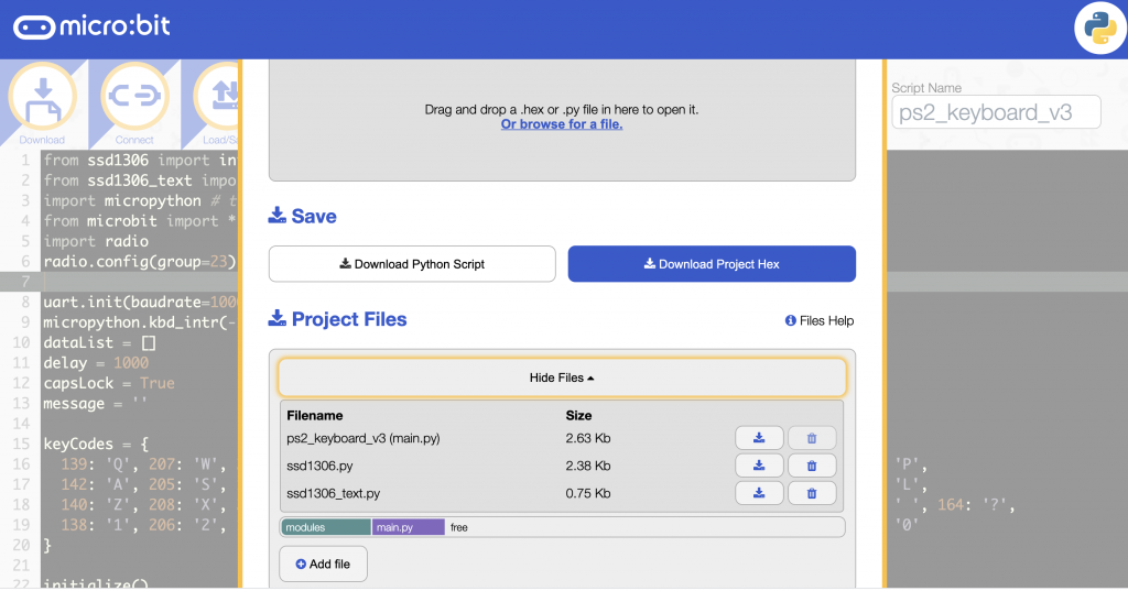
As well as the Python program at the end of this page, you’ll need to add two Python libraries ssd1306.py and ssd1306_text.py to make the OLED display work. You can do this using the online micro:bit Python editor. Click on the Load/Save button then ‘Show files’ then ‘Add a file’:

adding more files in the Python editor

Flash the 3 files to your micro:bit and you may need to press the reset button on the back of the micro:bit before first use. Your mileage may vary with the Baud rate, and the precise keycodes for each letter.

The receiving micro:bit will need some code on it like this:

from microbit import *
import radio
radio.config(group=23)
radio.on()
storedMessage = ''

while True:
    message = radio.receive()
    if message:
        display.scroll(message)
        storedMessage = message
    if button_a.was_pressed():
        display.scroll(storedMessage)

How to use it

Type your message and it should appear on the OLED display. Backspace will delete any errors. Caps lock key will toggle upper & lower case – the letter A in the bottom right-hand corner shows you which mode it’s in. Pressing enter will send your message by radio and clear the message.

How it works

It works using the principle of brute ignorance. I ignore the proper protocols for PS/2 keyboards and treat it as incoming serial data at 10000 Baud. This worked for me with the old Dell keyboard I found on the street. PS/2 keyboards send 3 codes every time you press a key: a key identifier, a release code when you let go, and it repeats the key identifier. The program looks these up and turns them into the appropriate letters every time 3 codes are received.

Improve it

- Change radio channel on the fly
- Add a Caesar cypher with selectable key – great for group interception / cryptanalysis games!

The main code

Here’s the Python code. You’ll also need those two Python OLED display libraries mentioned above, remember!

from ssd1306 import initialize, clear_oled
from ssd1306_text import add_text
import micropython # to enable disabling of accidental keyboard interrupt
from microbit import *
import radio
radio.config(group=23)

uart.init(baudrate=10000, bits=8, parity=None, stop=1, tx=None, rx=pin1)
micropython.kbd_intr(-1) # disable accidental keyboard interrupt
dataList = []
delay = 1000
capsLock = True
message = ''

keyCodes = {
  139: 'Q', 207: 'W', 210: 'E', 215: 'R', 150: 'T', 219: 'Y', 222: 'U', 161: 'I', 226: 'O', 231: 'P',
  142: 'A', 205: 'S', 145: 'D', 213: 'F', 154: 'G', 217: 'H', 157: 'J', 224: 'K', 224: 'K', 229: 'L',
  140: 'Z', 208: 'X', 209: 'C', 148: 'V', 152: 'B', 153: 'N', 220: 'M', 225: ',', 165: '.', 149: ' ', 164: '?',
  138: '1', 206: '2', 146: '3', 147: '4', 214: '5', 218: '6', 159: '7', 158: '8', 162: '9', 163: '0'
}

initialize()
clear_oled()
add_text(11, 3, 'A')
x = 0
y = 0

while True:
    add_text(x, y, '_') # cursor
    if capsLock:
        add_text(11, 3, 'A')
    else:
        add_text(11, 3, 'a')
    if uart.any():
        data = bytearray(1)
        uart.readinto(data, 1)
        dataList.append(data[0])
        if len(dataList) == 3:
            if dataList[0] in keyCodes:
                if capsLock:
                    letter = keyCodes[dataList[0]]
                else:
                    letter = keyCodes[dataList[0]].lower()
                add_text(x, y, letter)
                x += 1
                if x > 11:
                    x = 0
                    y += 1
                if y > 2:
                    y = 0
                    clear_oled()
                if x < 0:
                    x = 0
                if y < 0:
                    y = 0
                message = message + letter
            elif dataList[0] == 172: # toggle caps lock
                capsLock = not capsLock
            elif dataList[0] == 242: # backspace
                message = message[:-1]
                add_text(x, y, ' ')
                x -= 1
            elif dataList[0] == 131: # press F12 to review message
                display.scroll(message)
            elif dataList[0] == 236: # send message when enter pressed
                radio.on()
                radio.send(message)
                radio.off()
                add_text(0, 3, 'TX')
                message = ''
                x = 0
                y = 0
                sleep(delay)
                clear_oled()
            dataList = []
    display.clear()
Posted in microbit | Tagged , , , | Leave a comment

Read a PS/2 keyboard on a BBC micro:bit

What you’ll learn

  • That computer keyboards aren’t just switches – they need power to make them work
  • They comprise a matrix of buttons connected in rows and columns
  • Computers don’t read your keypresses directly – the keyboard contains a circuit board that does that
  • The keyboard sends keypresses to the computer as a stream of serial data – in effect numbers
  • Old-fashioned PS/2 keyboards send a code when you press a key and another when you release it
  • PS/2 keyboards aren’t, strictly speaking, just input devices. They also receive data from computers, for example to light the CAPS LOCK light output

Background

This is a testament to the power of ignorance. If you don’t know you can’t do something, sometimes you end up being able to do it.

For years I’ve wanted to connect a normal computer keyboard to a BBC micro:bit to make radio messaging and cryptography easier to use. I’ve seen, and indeed made myself, similar things on an Arduino, using libraries designed to read the subtle data coming from a PS/2 keyboard, frighteningly complex libraries in C++ that unpack every transition of every pulse of every bit of digital data.

Well, that’s not how I roll.

Previously I connected a thermal printer straight to a micro:bit and threw some serial data at it, and it worked first time, printing my message.

I never expected my home-made key-pad matrix, coded in utter ignorance, to work. But it did. First time.

Sometimes it’s helpful not to be fettered by knowledge and precedent, though not, I hasten to add, if you’re flying a plane, performing surgery or indeed running a country.

So I decided to take that approach to my micro:bit PS/2 keyboard problem.

What is a PS/2 keyboard anyway?

PS/2 keyboards are the old-fashioned type that came before USB – they often have round plugs, usually encased in purple plastic. (PS/2 mice tended to have green plugs.) They’re not especially easy to buy, at least not new, but people often throw them out, as we’ll see…

They’re just a matrix of buttons attached to a small controller running at 5 volts that turns key presses into serial data. Ok, the protocol is pretty horrible… an 11-bit word sent at anything between 10 and 16.7 kHz and comprising:

  • 1 start bit (always 0)
  • 8 data bits (least significant bit first)
  • 1 parity bit (odd parity)
  • 1 stop bit (always 1)

So I decided to ignore all that. I was walking the dog one day and found a PS/2 keyboard dumped at the side of the road, helpfully with the plug already cut off, and the plug also by the side of the road.

This was a sign.

The investigation begins

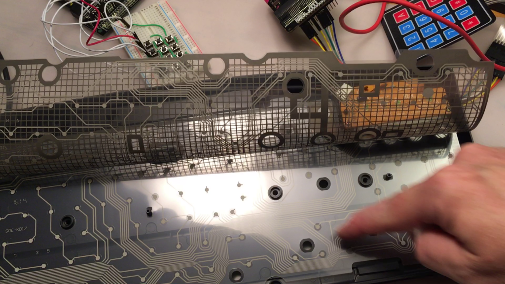
matrix inside a computer keyboard

Inside a computer keyboard

I took it home and opened it up. You can see in the picture above how the keys comprise two layers of plastic film that are pressed together to complete a circuit. The keys are arranged in a matrix, a grid of rows and columns.

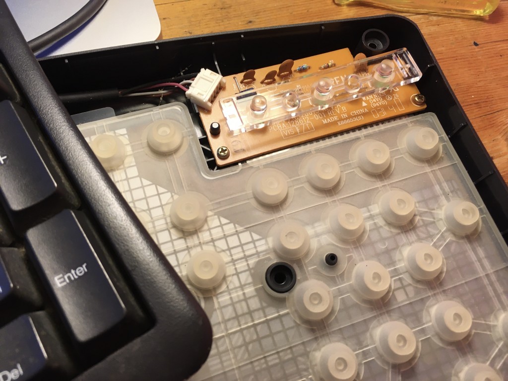
In the corner you can see the controller printed circuit board that contains the caps, num and scroll lock LEDs as well as the electronics that convert keypresses into a kind of serial data sent down the cable to the PC.

keyboard LEDs and membrane

keyboard LEDs and membrane

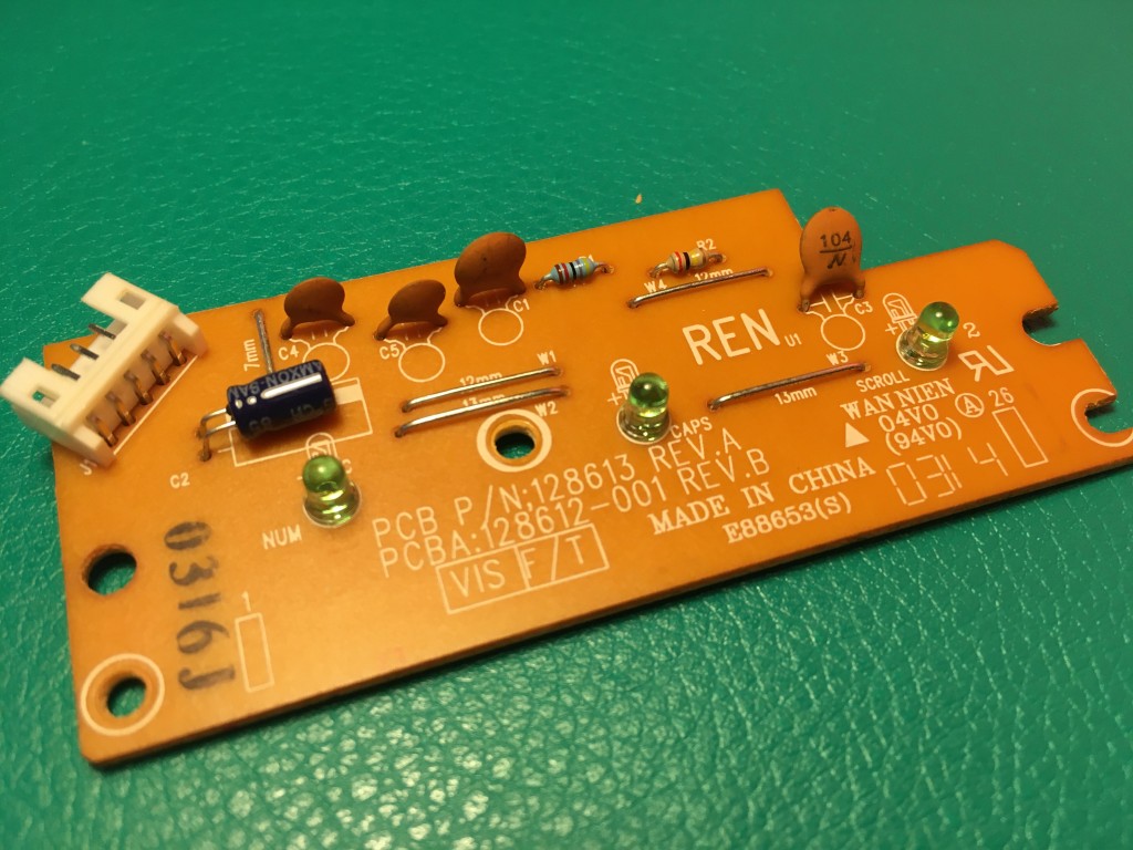
I hoped the controller PCB would helpfully show me what each coloured cable did. (There’s no standard for PS/2 cable colours).

detail of keyboard control PCB

detail of keyboard control PCB

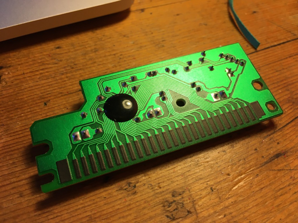
reverse of keyboard control PCB

reverse of keyboard control PCB

A few capacitors, LEDs, and an integrated circuit hidden under a blob on the back, and some labels, but alas nothing to identify the purpose of each wire going out to the plug. Even knowing the manufacturer and model number was no use either. Luckily, I still had the severed plug, so I was able to figure out that for this particular Dell keyboard:

Pink = 5v
Black = GND
White = Data
Brown = clock

5v. Hmm, the micro:bit supplies only 3v. Ignoring that, I connected the black wire to micro:bit GND pin and the pink to the micro:bit 3v pin. The LEDs lit up to show the keyboard was doing its power-on-self-test. The NUM LOCK light even lit (but not caps lock, I discovered that’s done in software by PCs, which send a signal back to the keyboard!)

So you can power a PS/2 keyboard off a micro:bit 3v supply – useful! No external power supply needed.

Now, what if I just ignore the clock wire, and pretend that the PS/2 keyboard is just sending serial data? We can read serial data on a micro:bit, I just need to know the Baud rate (the speed at which the data is being sent). That 10 to 16.7 kHz range sounds a bit scary, I tried a few different numbers and found that using 10,000 Baud I managed to get some sensible looking data from this program, with pin 1 connected to the white keyboard data wire and GND connected to the black keyboard ground wire, flashed onto a micro:bit using the online editor.

import micropython
# to enable disabling of accidental keyboard interrupt
from microbit import *

uart.init(baudrate=10000, bits=8, parity=None, stop=1, tx=None, rx=pin1)

micropython.kbd_intr(-1)
# disable accidental keyboard interrupt

while True:
    if uart.any():
        data = bytearray(1)
        uart.readinto(data, 1)
        display.scroll(data[0])

Pressing the letter Q, for example consistently produced 139, 248, 139.

Pressing A produced 142, 248, 142.

I knew from my reading (see, you do need a bit of knowledge) that PS/2 keyboards send a code when you press a key, then send a release code when you let go. So 139, 248, 139 really means ‘Q pressed’ ‘released Q’.

So all I needed to do was sniff the code for every key I was interested in and create a dictionary to look up the codes and turn them into letters. I’ve only bothered with the alphabet, numbers and some very basic punctuation so far, but I have implemented my own caps lock and backspace. (The caps lock light doesn’t come on, but one day…)

Key codes for other keyboards will probably vary, so use the sniffer program to make your own list if needed. You may also need to use a different Baud rate, but 10,000 worked for me with this Dell.

Secret radio message communicator project

Let’s put this new-found ignorance to use by building a super secret agent communicator! No-one will see you lurking in the bushes with a micro:bit and mahoosive Dell PS/2 keyboard you pulled from the trash!

Put this program on the receiving micro:bit:

from microbit import *
import radio
radio.config(group=23)
radio.on()
storedMessage = ''

while True:
    message = radio.receive()
    if message:
        display.scroll(message)
        storedMessage = message
    if button_a.was_pressed():
        display.scroll(storedMessage)

For the transmitter, use the code below. Remember you’ll need to attach pin 1 on the micro:bit to your keyboard’s data wire – mine was white but yours may not be. Also connect your micro:bit 3v pin to the keyboard’s power wire (pink in my case) and micro:bit GND pin to keyboard Ground (black on this Dell).

Type your message quite slowly. Letters will flash on the micro:bit display. The Caps Lock key toggles upper and lower case, but the shift key does nothing. If you make a mistake press backspace and it will delete the last character of your message.

Press button A on the micro:bit to review your message, and press button B to transmit it over radio. This also deletes the message because a good spy covers their tracks, right?

Sometimes it needs a reset when you power it up, so if it’s not working first time, press the reset button on the back of the micro:bit and see if that sorts it.

If you make something with this, please let me know and I’d be thrilled if you could credit me, this blog or my YouTube channel.

Enjoy!

import micropython # to enable disabling of accidental keyboard interrupt
from microbit import *
import radio
radio.config(group=23)

uart.init(baudrate=10000, bits=8, parity=None, stop=1, tx=None, rx=pin1)
micropython.kbd_intr(-1) # disable accidental keyboard interrupt if ctrl-C character received on serial input
dataList = []
delay = 250
capsLock = True
message = ''

keyCodes = {
  139: 'Q', 207: 'W', 210: 'E', 215: 'R', 150: 'T', 219: 'Y', 222: 'U', 161: 'I', 226: 'O', 231: 'P',
  142: 'A', 205: 'S', 145: 'D', 213: 'F', 154: 'G', 217: 'H', 157: 'J', 224: 'K', 224: 'K', 229: 'L',
  140: 'Z', 208: 'X', 209: 'C', 148: 'V', 152: 'B', 153: 'N', 220: 'M', 225: ',', 165: '.', 149: '_', 164: '?',
  138: '1', 206: '2', 146: '3', 147: '4', 214: '5', 218: '6', 159: '7', 158: '8', 162: '9', 163: '0'
}

while True:
    if uart.any():
        data = bytearray(1)
        uart.readinto(data, 1)
        dataList.append(data[0])
        if len(dataList) == 3:
            if dataList[0] in keyCodes:
                if capsLock:
                    letter = keyCodes[dataList[0]]
                else:
                    letter = keyCodes[dataList[0]].lower()
                display.show(letter)
                message = message + letter
            elif dataList[0] == 172: # toggle caps lock
                capsLock = not capsLock
                if capsLock:
                    display.show(Image.ARROW_N)
                else:
                    display.show(Image.ARROW_S)
            elif dataList[0] == 242: # backspace
                display.show(Image.ARROW_W)
                message = message[:-1]
            dataList = []
            sleep(delay)
    if button_a.was_pressed():
        display.scroll(message)
    if button_b.was_pressed():
        radio.on() # I'm in love with Massachusetts
        radio.send(message)
        radio.off()
        display.scroll('TX')
        message = ''
    display.clear()

You may also be interested in my post on making a your own key matrix using push buttons and a breadboard: http://www.suppertime.co.uk/blogmywiki/2020/08/microbit-computing-fundamentals/

Code can also be found here: https://github.com/blogmywiki/microbit-ps2-keyboard

Posted in Uncategorized | Tagged , , , , | 5 Comments