I’ve written before about how the KIM-1 (my brother’s) was the first computer I ever used, and how the very first programming I did as a child was 6502 assembler rather than BASIC. This led to me to make little machine code machines with micro:bits, and build my own 6502 breadboard computer, based on Ben Eater’s design but adding a hex keypad not a typewriter keyboard.
I was very strict when building my 6502 computer just to use tech that is roughly era-appropriate, eschewing microcontrollers for example. This puritanism is all well and good but caused me to neglect this very neat KIM-1 emulator for the Arduino Pro Mini: the KIM Uno.
You can download the PCB files and get it made yourself, it’s a very simple build and the components are very cheap, really just an Arduino, a couple of 7-segment LED displays, 24 buttons and a few resistors. I was reading the documentation when I got to the line ‘Actually, the software will run on any Arduino.’
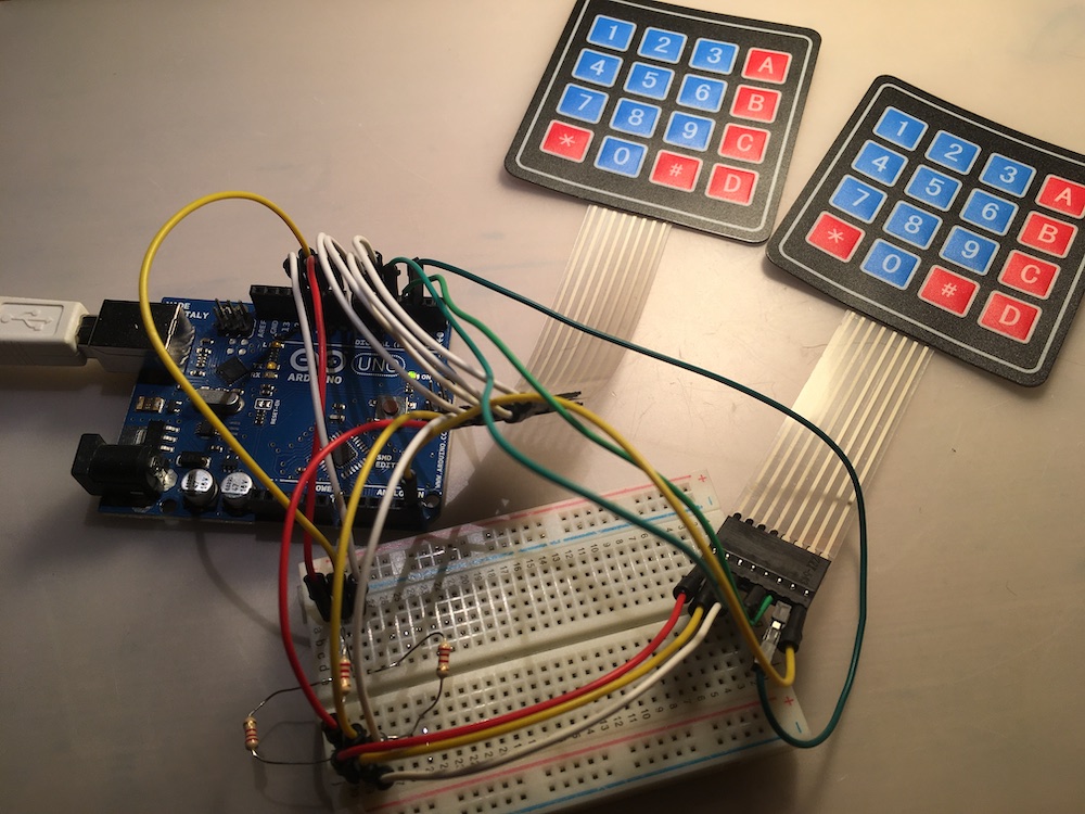
That got me thinking. Maybe I have all the bits I needed to build one of these lying around, assuming I used a breadboard instead of getting a PCB made. I certainly have millions of those little buttons, an Arduino Uno, piles of resistors, some 4×4 membrane keypads that would be easier to wire than individual buttons and some LED displays.
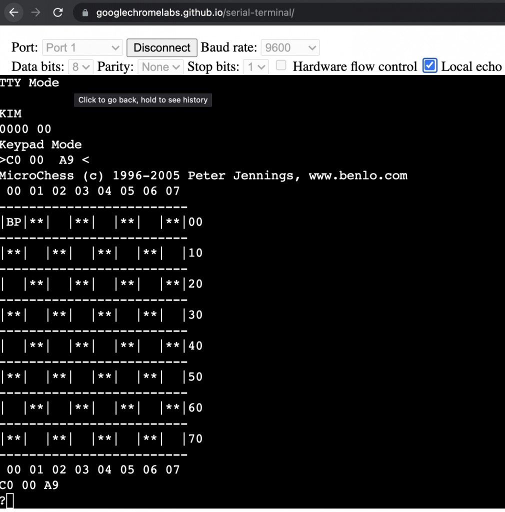
I compiled the code onto my Arduino Uno, and using a serial connection over usb connected to it from my laptop at 9600 baud using the awesome Chromelabs in-browser serial terminal. And it worked! You can switch between ‘normal’ mode and ‘luxury’ terminal mode by pressing the tab key. They call it ‘luxury’ mode because back in 1976 you’d have to have been seriously minted to be able to afford a teletype machine to connect to your KIM-1. Most people used the keypad and the 7-segment LED displays.
It’s a great emulator, with some useful utilities built in, as well as Peter Jennings’ Microchess: a working chess program in ~1K of machine code. You should read up on its creation, it’s an interesting story about a genius piece of coding.
I love programming. It is almost impossible to explain the joy of writing software to someone who has not experienced it.
First and foremost, it is an act of creation. From a simple thought, and the arrangement of a few words and symbols, a reality is created that did not exist before.
No other activity can keep you in the moment the way that writing software can. At each step, one hundred percent of your concentration is applied to the solving of the current problem. Time disappears.
Peter Jennings
So having proved the concept, I set about trying to build a KIM-1 clone using the KIM Uno’s software and schematics, and the bits and bobs I had lying around.
Snag 1: no breadboards.
Solution: rip apart another project and hope I documented it somewhere.
Snag 2: the keyboard layout is nuts. I mean really nuts.
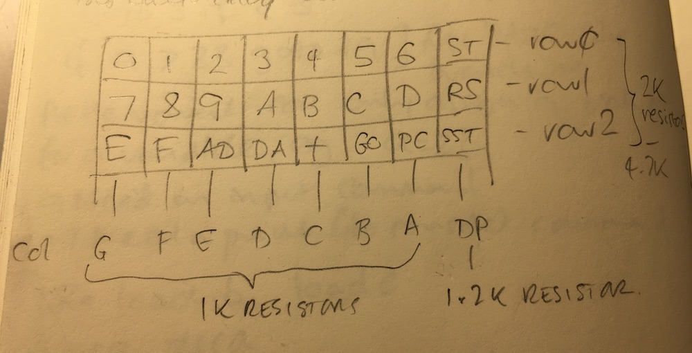
The original KIM-1 had 24 keys arranged in 6 rows of 4. Indeed so does the KIM Uno.
But that’s not how they’re wired. No, siree. It’s wired in a matrix of 3 rows of 8 buttons.
It’s actually very clever. I did wonder when adding my keypad to my own 6502 computer how the designers of the KIM-1 didn’t run out of GPIO pins. The answer was they actually shared the pins between the keypad and the display segments and switched them very, very quickly.
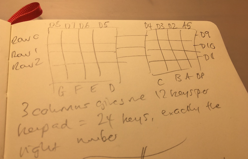
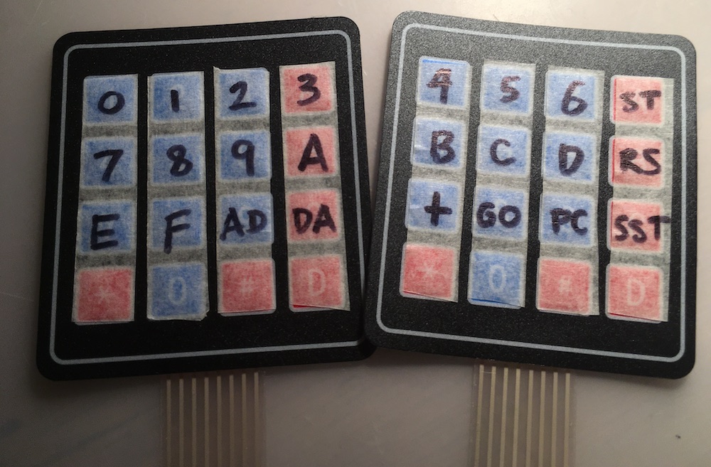
I’ve wired up individual buttons to make keypads on breadboards before, and it’s a real pain, so I decided to stick with my plan to use two 4×4 membrane keypads and not use the bottom row. I need to relabel the buttons, but it works!
Here’s how to wire it up. With the membrane keypads, I’ve numbered the pins looking from the front, so pins 1-4 are the rows and pins 5-8 are the columns. You need to join the rows together to make 1 very wide keypad. So, connect row 1 on keypad A to row 1 on keypad B. Do the same for rows 2 and 3. These become rows 0, 1 and 2 on the KIM keyboard. Connect rows 0, 1 and 2 via a ~2K ohm resistors to pins D9, D10 and D11 respectively on the Arduino.
Now wire up the columns.
Keypad A pin 5 / column G -> Arduino pin D8
Keypad A pin 6 / column F -> Arduino pin D7
Keypad A pin 7 / column E -> Arduino pin D6
Keypad A pin 8 / column D -> Arduino pin D5
Keypad B pin 5 / column C -> Arduino pin D4
Keypad B pin 6 / column B -> Arduino pin D3
Keypad B pin 7 / column A -> Arduino pin D2
Keypad B pin 8 / column DP -> Arduino pin A5
Snag 3 – the displays
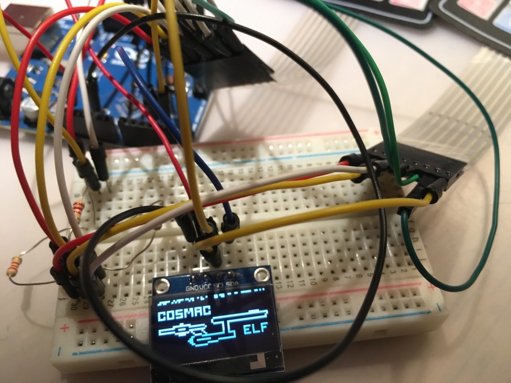
It turns out that my lucky bag of random 7-segment LED displays wasn’t so lucky. They’re all common cathode, when the design for the Kim Uno needs two common anode displays. They’re very cheap to buy, but while I wait for one to arrive, I noticed that you can also attach an OLED display to it, if you uncomment a line in the config file and connect the display’s data pin to A4 on the Arduino and the display’s clock to Arduino pin A4.
The sketch will only compile for a Uno if you remove almost all the sample code, and you get this intriguing display which doesn’t make a whole lot of sense (there is separate firmware to turn your KIM Uno into a Cosmac Elf) – I was expecting to see the LED display mirrored on the OELD!
I’ll have to order a couple of common anode LED displays and maybe an Arduino Pro Mini and report back. Oh, and I’m probably going to need a bigger breadboard.
The keypads relabelled with masking tape and Sharpies. The layout is a bit crazy, but hey the original KIM-1 keypad layout doesn’t make a lot of sense to me either, and this saved a metric tonne of fiddly button breadboard wiring.
We’re going to need a bigger breadboard
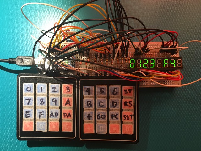
I got some common anode LEDs and made this. It worked. Almost. One segment of the LED display didn’t light and I couldn’t figure out why:
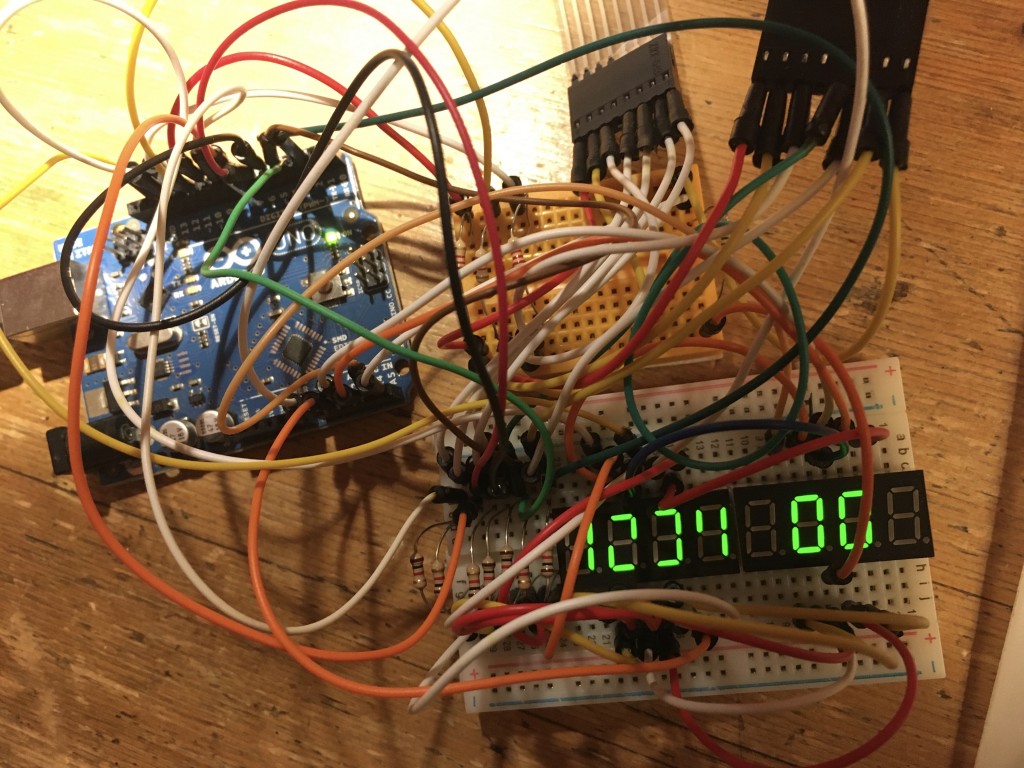
So I got a bigger breadboard and wired it all up from scratch, spacing everything out a bit more. I missed one jumper out and one was in the wrong hole, but once I’d fixed that, I have a working self-contained Kim-1 clone / simulator! You can use the keypads and LEDs and the serial port on a computer as well, living the 1976 computing dream!
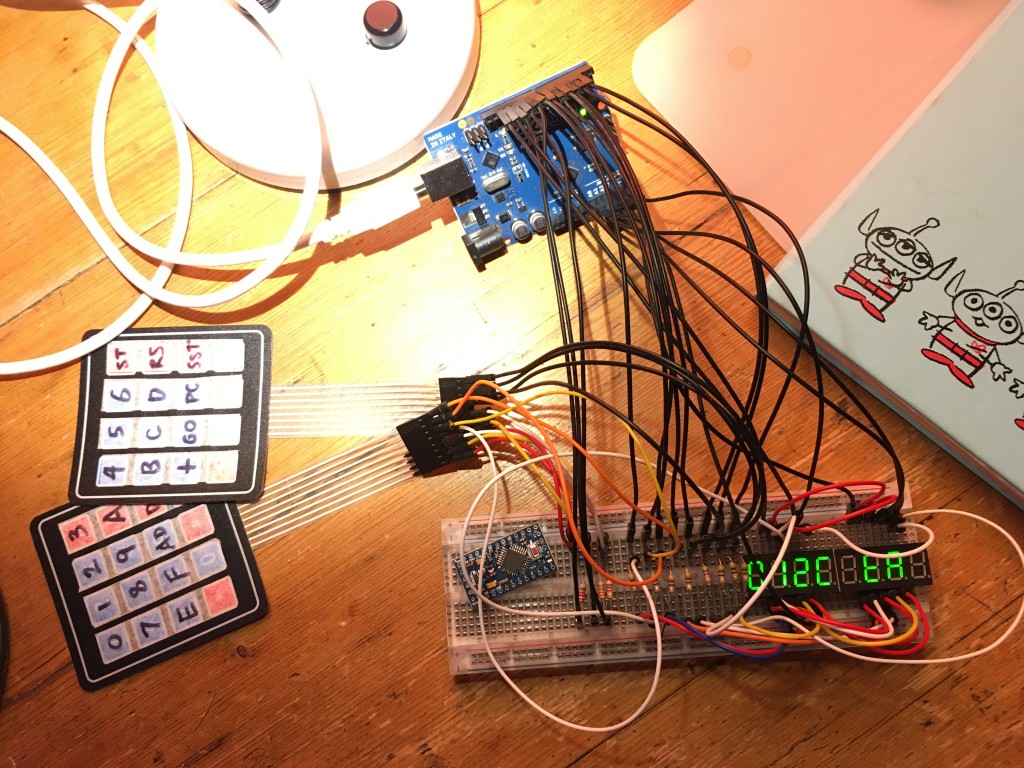
Next step will be to put it in some kind of box that supports the keypads, and then to replace the Arduino Uno with the Arduino Pro Mini – pictured at a jaunty angle on the breadboard. I just realised that as it has pins running all the way round it, it’s not going to work on a breadboard. Doh! I guess I could get another small Arduino that does, or use male to female jumper wires and let it float.
Arduino Nano update
I made a more compact version using a cheap Arduino Nano clone that fits on the same breadboard as the LEDs and the resistors. I bought a pre-soldered one to save time and swearing.
A couple of things to note:
- It was hard to get the pins of the Arduino into the breadboard. In the end I had to work a jumper wire down each row prior to insertion to loosen the holes up a bit.
- At first the sketch wouldn’t flash on to the Arduino. I got the error message ‘stk500_getsync() attempt 1 of 10: not in sync: resp=0×00′. Turns out this was because I needed to select old firmware in the Arduino IDE. Go to Tools > Processor > ATMega328P (Old Bootloader) before flashing the Kim UNO code to a cheap Nano clone.
- I successfully powered this off a PP3 / 9v battery, making it completely self-contained. Unplug the Arduino from any other power source like USB, connect the +ve battery terminal to the Arduino’s Vin pin, and the battery -ve terminal to GND on the Arduino.

