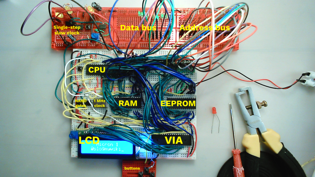
I last posted way back in October 2020 about my progress with my Ben Eater-style 6502 breadboard computer. Having my own Kim-1 or Acorn System 1 type single board computer was a childhood dream, and several decades later I was building my own, finally feeling I could look that kid in my school computer club who built his own SC/MP-based computer in the eye. Finally. Forty years later. But, finally.
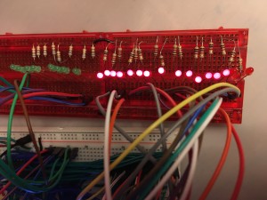
I had managed to connect an EEPROM which I programmed with one of Ben’s programs, and I made a simple clock from some 555 timers that allowed me to single-step or run programs very slowly. I don’t have an Arduino Mega to use for debugging, so I diverged from Ben’s layout by adding 8 green LEDs across the data bus and 16 red LEDs across the address bus. This decision proved to be one of my better ones.
I added a 65C22 VIA (versatile interface adaptor) and managed to get text to print out on an LCD display. I then decided to rejig the layout a bit to give better access to my data and address busses, and to put the EEPROM in a more accessible place – and that’s when disaster struck.
Nothing worked any more. I could not fix it. I decided I had used the wrong wires, damaged the breadboard, broken something fatally and put it away in a box and left it for a few months.
Picking it up again, I’ve now got it working, added RAM so that you can use the stack, and hence use subroutines. You can’t use subroutines in 6502 assembly language without RAM, because it puts the return address on the stack, and without RAM you have no stack!
I also added a 1 MHz crystal oscillator clock, and today I got interrupts working. I didn’t bother with Ben Eater’s binary to decimal conversion code, I just made it print a different piece of text when you press a button. But it works! I now want to add more buttons, and I know that involves port A on the VIA, but I’ve caught up with Ben Eater now, I need him to make some more videos!
Some words of advice to those of you thinking of making a breadboard computer from scratch:
It’s a good idea!
I’ve re-learnt and learnt some more assembly language, debugged a program literally bit-by-bit – you can’t get closer to the metal than that! I’ve also discovered how CPU interrupts work, and generally found working with fundamental building blocks of hardware and software very satisfying. And yes, resilience… debugging in binary, for an hour… oddly therapeutic.
Slave to the layout
You’re probably better off following Ben’s layout slavishly if you’re new to this. But…
 Blinkenlights are good
Adding data and address bus blinkenlights is very useful, especially if you don’t have an Arduino Mega to monitor the ports. You could probably add them on separate breadboards and keep Ben’s layout if you’re clever with the wiring. I only fixed my faulty board by single-stepping through a program, and reading every address and piece of data in binary, converting it to hex and decoding it. I discovered that my program wasn’t ever returning from a subroutine, meaning a likely RAM problem. And sure enough, I found a loose wire on the RAM chip. It took me an hour, and I now can read LDA and STA instructions in binary, but it worked. I hadn’t broken anything fatally, it was just a loose wire. Plus, blinkenlights are cool.
Burning EEPROMs
You get to burn EEPROMs. Burning EEPROMs is magic. It’s cool. And you don’t even need UV light to erase them any more.
How do you make your breadboards look so messy?
Watch Ben’s video on how he makes his breadboards so neat. He hadn’t posted it when I started. That’s my excuse.
Like clockwork
Hmm, the clock. I skimped on my clock design, thinking I knew best. Sure I have no logic probe, no oscilloscope, no Arduino Mega to read the busses, but how hard could a darn clock be to make, right?
Well, here’s the thing. As soon as I added the 1 MHz crystal clock, things just started working, well, not just faster (obviously), but better. More reliably. I still get the occasional glitch, but generally my computer seems to work so much better now.
So I now think a lot of the problems I had earlier were with my clock, not giving clean pulses. So if you want to build a clock that allows single-stepping and variable slow speeds (which I think is essential for this kind of project, for learning and debugging), then put in the effort and build a nice clock. Listen to Ben. Even if you think his design is over-engineered.
Where does it go from here?
Not down to the lake, I fear.
Ideas…
- Add moar buttons. No idea how to code them!
- Add a hex display to the data bus – Ben’s video on using EEPROMs to replace a squillion logic gates is very cool. The chip he uses is now obsolete, what would be a good replacement?
- Eventually some kind of monitor program and a hex keypad at least. This is a very far-off goal.
- Add a thermal printer, Aim-65 style.
Code
My modified versions of Ben Eater’s assembly language programs can be found here: https://github.com/blogmywiki/6502


Great work! You’re brave to do this without even a logic probe. :)
You could use almost any parallel EEPROM for the hex display decoder. It’s difficult to find ones that don’t have vastly more memory than is required. The extra space can be used to provide more features. For instance, I designed a four-digit decoder that has hex, decimal, signed decimal, and octal display modes using an AT28C64B (and that only uses half the available space).
Sounds like a great idea, thank you!