I’ve been watching Wifi Sheep’s Arduino simple BASIC computer builds and this cool little project using LCD and OLED displays with interest, and I thought I might have a go at building something similar myself with parts I have lying around including an old PS/2 keyboard I found on the street, an Arduino UNO and a Pro Mini I bought for the KIM-1 clone project but never used.
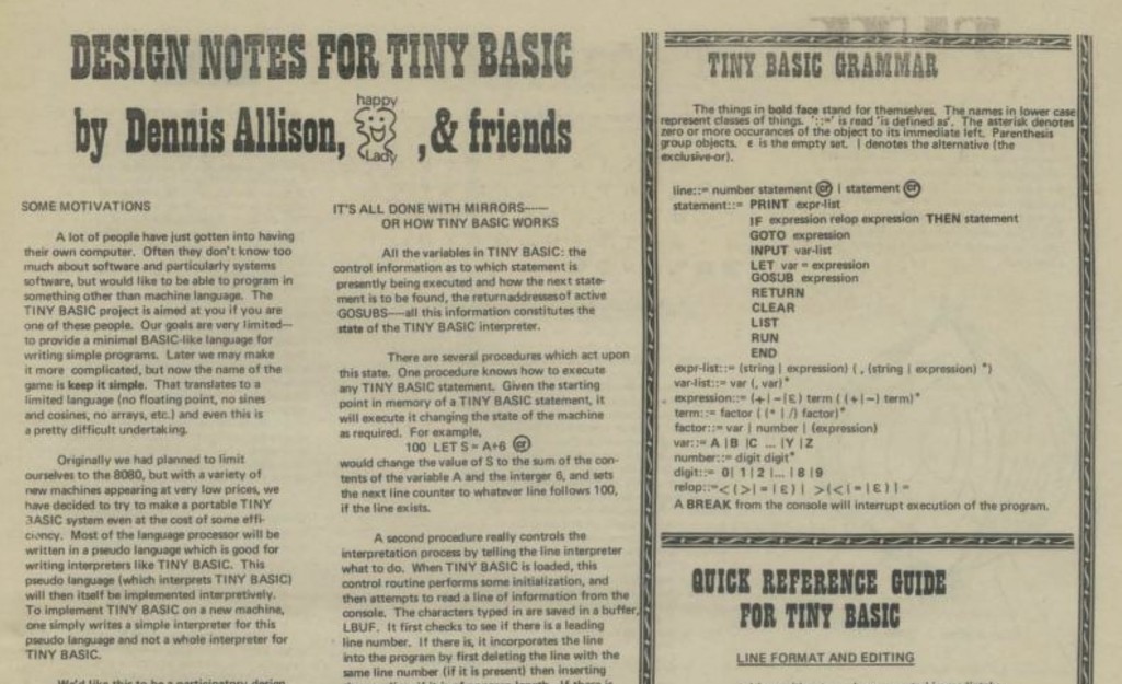
As a language, TinyBASIC may be ‘awful’ as someone told me, but it has an interesting history. It stemmed from a challenge made in the September 1975 issue of the People’s Computer Company magazine (later better known as Dr Dobb’s Journal) to write a simple, free version of BASIC. Around this time two dudes called Bill and Steve were getting annoyed at people illegally copying their new MicroSoft BASIC, and TinyBASIC was written to give people a free, legal, ‘copyleft’ alternative. I really recommend browsing old issues of PCC magazine, there are some great articles in there some of which are still relevant today. (I was also inspired by reading about the origins of TinyBASIC to create my own ultra-simple text-based language for the BBC micro:bit.)
You can run Tiny BASIC on a BBC micro:bit, but for this project I decided to make some Tiny BASIC computers using some Arduinos to see if I could make a standalone computer with keyboard and display.
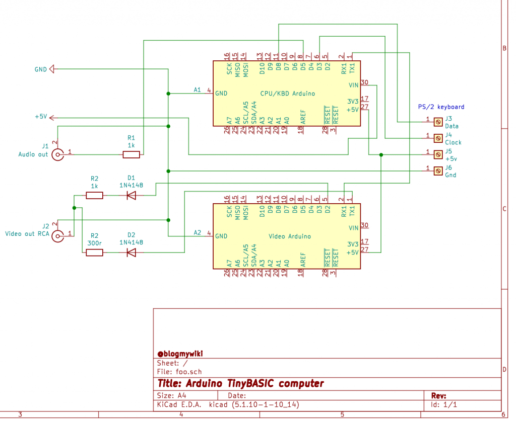
I used this project from a few years ago by Rob Cai as the basis. Like the Wifi Sheep computer, it uses two Arduinos, one to handle keyboard input and run TinyBASIC, and the second to act as a kind of video card generating surprisingly hi-res video using the MRETV software. It turned out I had almost all the components I needed to build this, except some diodes. So while I was waiting for the diodes to arrive in the post, I pondered alternative output devices…
It occurred to me that I have a serial thermal printer, and I could maybe use that as an output device, a bit like the old Rockwell AIM-65 computer from 1978. And it sort of worked! I just changed the baud rate in the Arduino program running TinyBASIC to 19200 baud to match the printer, and connected the TX pin of the Arduino to the RX pin of the printer. As you can see from the video, I still needed a serial console on a laptop so I could see what I was typing, and the last line of text output was hidden by the printer case, but it basically worked.
I got thinking about some kind of hybrid computer with an LCD or OLED display for text entry and showing what you’re typing, and a thermal printer for hard copy and program output. I couldn’t be bothered to solder up pins to my spare Arduino Pro Mini, so I decided to see if I could use a micro:bit instead to drive an OLED display. The micro:bit is great for quick prototyping – no soldering required and it’s a breeze to program in MakeCode or Python rather than C++ used by the Arduino.
First I had to do some level shifting: the Arduino works at 5v and the micro:bit at 3v, so I used a 1K and 2K resistor as per this guide to make a voltage divider, dropping 5v to just over 3v so I didn’t damage the micro:bit. So, the serial TX pin of the Arduino is connected to a 1K resistor, the other side of which is connected to Pin 1 on the micro:bit and also to a 2K resistor which goes to ground. It’s a very crude level shifter and it may explain why I had to reduce the baud rate, but it does seem to do the job. The grounds on the micro:bit and Arduino are linked, and I back-powered the micro:bit from the 3.3v pin on the Arduino UNO. I also used a MonkMakes I2C breakout board to connect the OLED display to the micro:bit and used two Python libraries ssd1306.py and ssd1306_text.py to drive the OLED display.
As you can see that was a bit flaky, but slowing the baud rate down to 1200 and adding some delays at the start of the Arduino TinyBASIC program worked a treat:
All good fun and confirms the idea is sound, but alas the text is too big and the display too small, so my next step will be to replace the micro:bit with an Arduino that can print smaller text on an OLED display – or maybe even a 4 line LCD display? And if that doesn’t prove workable, then I just may well fall back on making a machine that has an old-fashioned composite video output!
FYI, the current version of my micro:bit Python program looks like this. It just polls pin 1 for serial data and prints anything it receives on the OLED display. If it gets confused it shows a ‘?’ on the micro:bit’s LED display.
from microbit import *
from ssd1306 import initialize, clear_oled
from ssd1306_text import add_text
import micropython
# baudrate was 19200 for thermal printer
uart.init(baudrate=1200, bits=8, parity=None, stop=1, tx=None, rx=pin1)
micropython.kbd_intr(-1) # disable accidental keyboard interrupt

initialize()
clear_oled()
x = 0
y = 0

while True:
    if uart.any():
        msg_bytes = uart.readline()
        msg_str = str(msg_bytes, 'UTF-8')
        if len(msg_str) > 0:
            try:
                for char in msg_str:
                    if ord(char) > 31:
                        add_text(x, y, char)
                        x += 1
                        if x > 11:
                            x = 0
                            y += 1
                        if y > 2:
                            y = 0
                            clear_oled()
                        if x < 0:
                            x = 0
                        if y < 0:
                            y = 0
                    elif ord(char) == 13:  # new line / CR
                        x = 0
                        y += 1
            except:
                display.show('?')
Update 1 - adding a 2nd Arduino with an OLED display
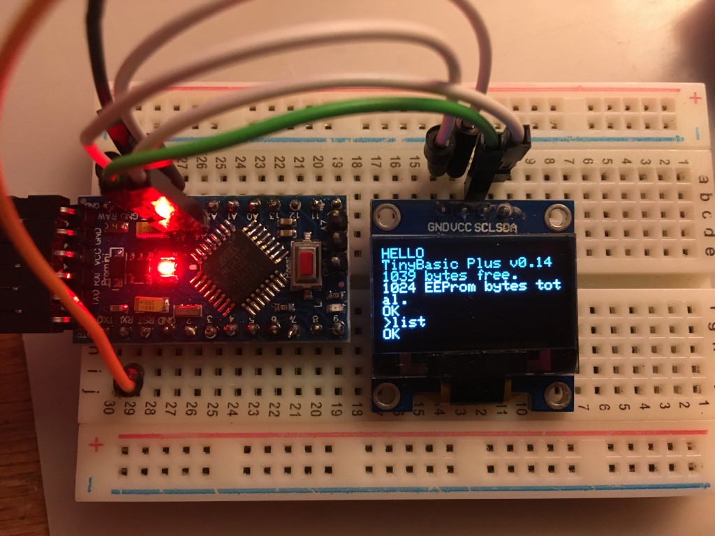
Despite hating soldering so much previous me hid my solder from myself in the loft, I've made progress replacing the micro:bit with a cheap Arduino Pro Mini clone driving the OLED display with a smaller, and hence more useful, font.
I just connected the serial TX pin on the Arduino UNO running BASIC and polling the keyboard to the serial RX pin on the Arduino Pro Mini that's driving the OLED display. Despite my truly awful soldering of pins on the Pro Mini, it works!
Here's the wiring for the OLED on the Pro Mini:
Arduino > OLED
--------------
Pin 4   > SDA
Pin 5   > SCL
VCC     > VCC
GND     > GND
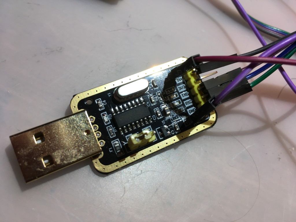
The Pro Mini doesn't have a USB adaptor, so you need something like an FTDI adaptor to bridge between the Pro Mini and a computer running the Arduino IDE. My adaptor needed 2 extra pins soldering (CTS and RTS) and I had to figure out what they connected to. In the highly unlikely event anyone has the same FTDI adaptor and is wondering how to connect one to a Pro Mini, here's the wiring you need:
Pro mini > FTDI adaptor
-----------------------
DTR      > RTS (data terminal ready > ready to send)
TX       > RX
RX       > TX
VCC      > 5v
GND      > GND
GND      > CTS (clear to send)
You'll also need to disconnect anything from the Pro Mini's serial input before you flash a program or it won't work. Also make sure that you have the correct voltage FTDI adaptor - mine has jumpers that allow you to select 3v or 5v, I've selected 5v as I have a 5v version of the Arduino Pro Mini.
Here's the Arduino program I wrote to put text received on the serial port on the OLED display. It uses the Adafruit SSD1306 library. Note that I had to change the I2C address from the Adafruit code example to 0x3C for my display, and if you try this you may also need a different number. Also it's still using the very slow serial transfer rate of 1200 baud I was using with the micro:bit, which almost certainly could be speeded up.
#include <Wire.h>
#include <Adafruit_SSD1306.h>

#define SCREEN_WIDTH 128 // OLED display width, in pixels
#define SCREEN_HEIGHT 64 // OLED display height, in pixels

int incomingByte = 0; // for incoming serial data
int x = 0;   // counters for working out rough cursor position to clear screen when full
int y = 0;

// Declaration for an SSD1306 display connected to I2C (SDA, SCL pins)
Adafruit_SSD1306 display(SCREEN_WIDTH, SCREEN_HEIGHT, &Wire, -1);

void setup() {
  Serial.begin(1200);

// you may need to change 0x3C depending on your type of OLED display
  if(!display.begin(SSD1306_SWITCHCAPVCC, 0x3C)) {
    Serial.println("SSD1306 allocation failed");
    for(;;);
  }
  delay(1000);
  display.clearDisplay();
  display.setTextSize(1);
  display.setTextColor(WHITE);
  display.display();
  display.setCursor(0, 0);     // Start at top-left corner
  display.cp437(true);         // Use full 256 char 'Code Page 437' font
}

void loop() {
  if (Serial.available() > 0) {
    incomingByte = Serial.read();
    display.write(incomingByte);
    display.display();
    ++x;
    if (x == 20) {
      x = 0;
      ++y;
      }
    if (incomingByte == '\n') {
      ++y;
      x = 0;
      }
    if (y == 8) {
      display.clearDisplay();
      display.setCursor(0, 0);
      y = 0;
      x = 0;
    }
  }
}
I think the magnifying glass adds a touch of Brazil… pic.twitter.com/QN51YGfkjp
— blogmywiki (@blogmywiki) September 3, 2021
Update 3 - video out
I think the best solution for this project would be a 256 x 64 pixel OLED display driven by an Arduino. They cost around £27, compared with less than £5 for a 128x64 OLED, but as someone pointed out to me on Twitter, a wide OLED would have similar dimensions to a Radio Shack TRS80 Model 100, which is exactly the vibe I'm aiming for.
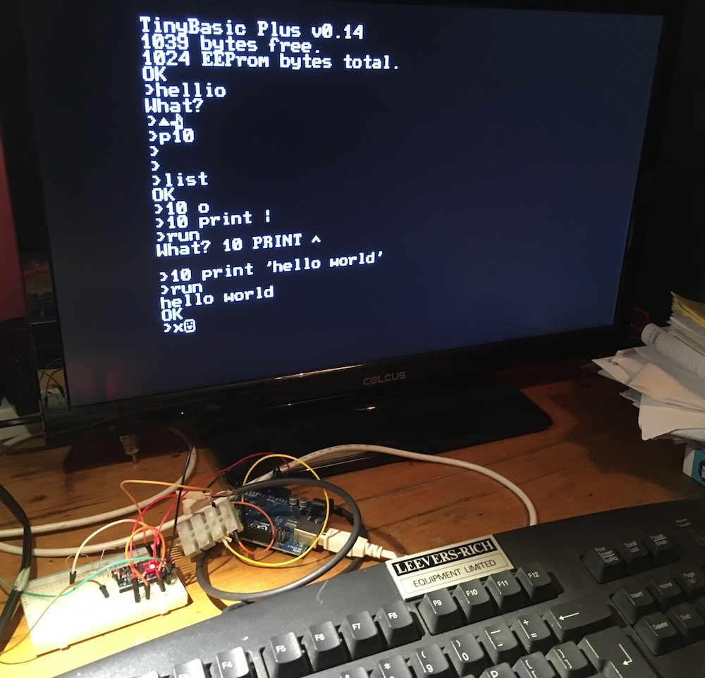
So, before I get one of those, I decided to see how the video out version in Rob Cai's original project worked. It was amazingly simple to make. I removed the OLED display and repurposed the second Arduino as a 'video card'.
First I added the MRETV library to the Arduino IDE as per his instructions, then I flashed Rob's TVtext_slave.ino file to my second Arduino. I found 1 typo in this file I had to fix. The line
#include <MrETV.h>
should read
#include <MRETV.h>
(capital letter R).
As per Rob's guide, I connected pin D2 on the Arduino via a switching diode to a 1K resistor. The other end of the 1K resistor is connected via a diode to TX pin 1 on the Arduino. Where the two resistors join, I tapped off a wire that goes to the centre pin on an RCA / phono plug that provides the video out. Connect this plug to the composite video input of a TV.
I've not connected the sound yet, so I'll do that next then see if I can improve the keyboard mapping, maybe wire up a reset button and investigate if I can get a delete key working. And maybe even see if I can modify the font!
I've also been messing about with KiCad for the first time, and I think this is what Rob Cai's circuit looks like:
