Last time I added a 4×4 keypad to my 6502 breadboard computer so I can enter opcodes as hexadecimal numbers, but I was worried that I needed more keys and didn’t have enough I/O pins left.
To make a self-contained computer like a Kim-1 or an Acorn System 1, you need to be able to enter not just opcodes for instructions, you need function keys as well to step forwards and backwards through the program you enter, start it running and stop it.
I found that I did have one single I/O pin left on the VIA (versatile interface adaptor) chip – PA4. It is possible to daisy chain another 4×4 keypad using some logic, but I don’t need 16 more keys (although you could make a full alphabet keyboard that way!). So I decided to make my own simple shift key.
I added a push button, and some code to read the status of PA4. The idea is that pressing unshifted keys caused them to display on the LCD, but if I press shift and D it will step forwards through memory, shift and C will step backwards. Baby steps, if you like, towards making a full monitor program.
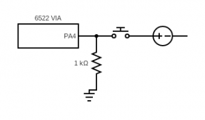
Thinking this was just a simple matter of sending 5v up it when the button is pressed, I just wired it between PA4 and the 5v rail. And at first, it worked! Press keys – they displayed. Press shift D, it steps forward. But shift got stuck. I let go of the shift key but it carried on behaving as if shift was still pressed. Why?
You’re probably way ahead of me here, but it was a very useful learning point. I’d heard of pull-up and pull-down resistors in logic circuits before, I knew they were a thing, but only now did I understand at a very fundamental level why they may be needed.
Pressing my shift button sent 5v up pin PA4 and changed its status from 0 to 1. But when I let go, what changes it back again? You literally need something to pull it back down to ground, 0v. Hence the need for a pull-down resistor:
Pressing any key generated a signal on the DA (data available) pin which I use to trigger an IRQ (interrupt request) on the processor via the 6522 VIA chip. I modified my IRQ code like this.
irq:
  lda PORTA		; read contents of PORTA into memory
  sta inport
  lda inport		; read the state of PORTA back into A again - needed?
  and #%00001111	; strip out all but the key encoding
  sta inkey		; store the key value in memory
  lda inport		; read the state of PORTA back into A again
  and #%00010000	; read the shift key input
  beq no_shift		; if zero flag set, no shift key is pressed
  lda #$01		; if shift pressed, set shift flag
  sta shift
  jmp shift_cont	; skip clearing the shift flag, obvs
no_shift:
  lda #$00		; if shift not pressed, clear shift flag
  sta shift
  jmp update		; if no shift key is pressed just update the display
shift_cont:		; there was a colon missing here but it worked!
  lda #%00001111	; is the key 'd'?
  cmp inkey
  bne key_c		; if not, jump to next test
  iny			; if it is 'd', increment the location being displayed
key_c:
  lda #%00001101	; is it 'C'?
  cmp inkey
  bne update		; if not, skip decrementing
  dey			; if it is, decrement location index
update:
  jsr lcd_mon
  rti
So, some real progress. I can type hex numbers on the display and use a shift key to gain extra function keys when I need them. Next step is to enter and store real data or opcodes in memory using the keypad.
Source code: https://github.com/blogmywiki/6502
Posts in this series
Next – Part 7
Part 5
Part 4
Part 3
Part 2
Part 1


Hi Giles. I came across your website and it was in line what I wanted to build a simple hex keypad / display computer. Your work was easy to follow and understand. Great work.
I have added another row of keys to the 4×4 matrix using a diode and Nand gate as in the 74c922 datasheet. I can use these keys to go to next location or backwards or run program by jumping to 0300 as in your monitor program. I can email the details if you are interested.
Hi Sonny – that sounds great! If you have any info or diagrams I’d be delighted to share them on the blog. Glad you found my keypad addition useful.
best wishes
Giles
Thank you very much. You can find the details in using this link – https://imgur.com/a/VyHf1xb