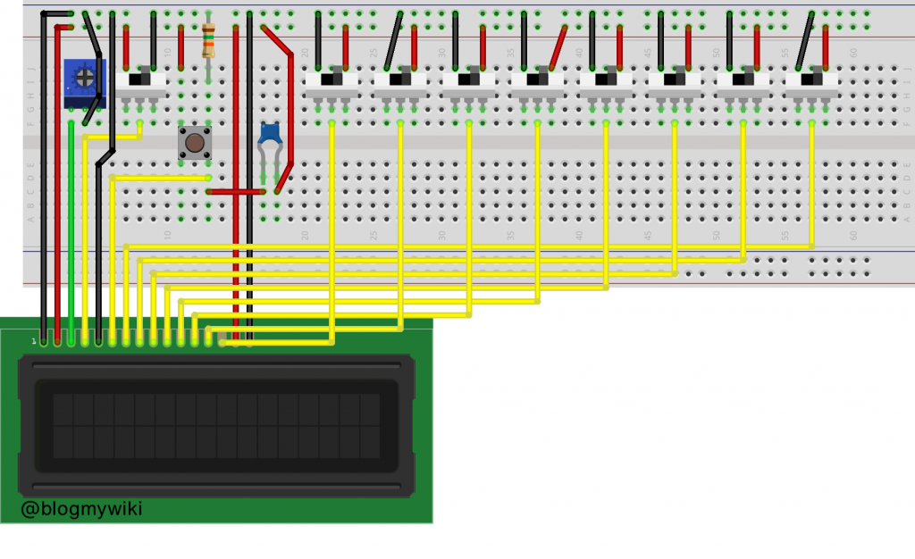
There’s a YouTuber called the 8-Bit Guy who’s made a fantastic project where he gets text on an LCD display just using switches instead of a micro-controller or computer. He made his (video below) in a nice box with chunky switches, and I thought I’d try and make one on a breadboard.
This was a mistake, but I did, just about, get it to work and it makes an interesting project to learn a bit about low level logic, binary maths, data representation and so on with some very simple and inexpensive parts. It’s a good gateway to building a more complex project like a breadboard computer, which I plan to do this winter and it will use a display just like this so it’s all good practice.
Building it
Here’s what I used:
- a 2 x 16 alphanumeric LCD display (old-fashioned parallel type, not one with an SPI interface)
- 9 tiny single-pole dual-throw switches
- a push-button
- a 0.1uF capacitor to debounce the push-button
- a variable resistor
- a 4.7k ohm resistor
- a breadboard
- jumper wires
- a USB lead with one end stripped to provide 5v power
Here’s how I wired it up – I’d be very happy to be corrected on my inevitable mistakes – I am not an electronics expert in any way!
The LCD pin wiring goes like this from left to right:
LCD pin
 1 GND
 2 +5v
 3 variable resistor for contrast
 4 centre pole of register select switch
 5 GND
 6 one side of the enter button
 7 to centre pole of data switch
 8 to centre pole of data switch
 9 to centre pole of data switch
10 to centre pole of data switch
11 to centre pole of data switch
12 to centre pole of data switch
13 to centre pole of data switch
14 to centre pole of data switch
15 +5v for backlight
16 GND for backlight
Using it
Switch the program select switch to the 0v / GND position and enter some control codes. I tried a few different ones but found that this (sometimes) worked to select two line mode. Put the data switches in each position, then press the ‘enter’ button:
0000 1111
0011 0000
Then to enter text, switch the program select switch to the +5v position, alter the switches to the positions of binary representations of ASCII characters, and press the enter button after each one.
H 0100 1000
E 0100 0101
L 0100 1100
L 0100 1100
O 0100 1111
  0010 0000 (space)
W 0101 0111
O 0100 1111
R 0101 0010
L 0100 1100
D 0100 0100
The little breadboard switches are far too fiddly and prone to flying out of the board, so if I were to make this properly I would go the same way as the 8-Bit Guy and use big switches in a proper box.
If you fancy connecting one of these to a BBC micro:bit, check out my previous post: http://www.suppertime.co.uk/blogmywiki/2019/04/lcd-microbit/
Related videos
The 8-Bit Guy video that started me making this:
A Ben Eater video on adding LCDs to a breadboard computer which has very useful stuff on the control codes:

