I’ve made a few projects recently using 4 x 4 membrane keypads with the BBC micro:bit. I made a calculator, then a wireless communicator and most recently I recreated the 1970s game Mastermind.
I thought it might be interesting to focus on how keypads (and by extension, computer keyboards) work and unpack some more of the learning around this. I think this shows how good the BBC micro:bit is understanding how technology works at a very fundamental level, but at the same time being quite simple and accessible, using block coding thanks to Microsoft MakeCode, and simple components thanks to the design of the micro:bit itself.
There are, for example, many Arduino projects for wiring up keypads but they are difficult to program, using C++ in the Arduino IDE which isn’t very child friendly, and yet at the same time using provided Arduino libraries actually shields you from learning what’s going on at a fundamental level.
Here we’ll see how the micro:bit gives you the best of both worlds: a simple, friendly online code editor, and yet you’ll write your own program to scan and interpret keypresses.
While I was waiting for my ready-made keypads to arrive, curiosity got the better of me. I had a breadboard and a bag of around 100 tiny push-buttons and decided to see if I could make my own. I knew keypads were arranged in a grid or matrix, but I was curious to know exactly how they were wired together.
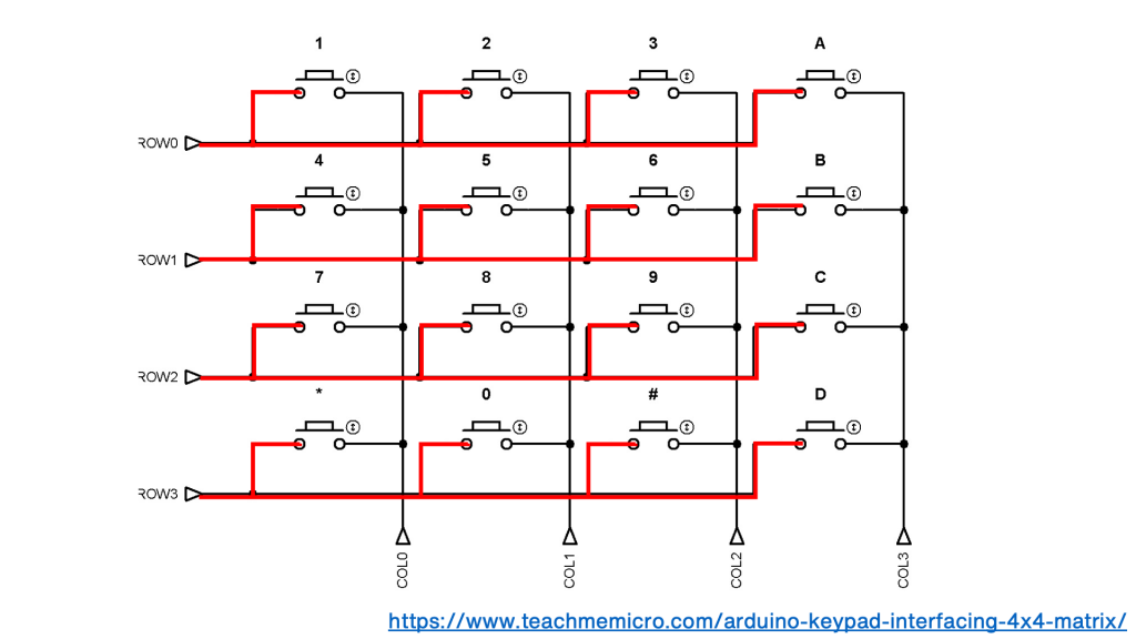
Looking at a circuit diagram of a keypad you can see that the same side of each button, the left side here, is connected together, row-by-row:
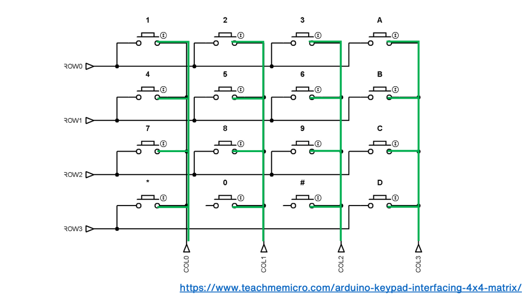
In each column the other side of each switch is connected together:
This gives you 8 wires for a 4 x 4 keypad. That sounds like a lot, but if you connected each key separately to a computer, calculator or microcontroller you’d have 16 wires plus a ground or earth wire connected to each button as well.
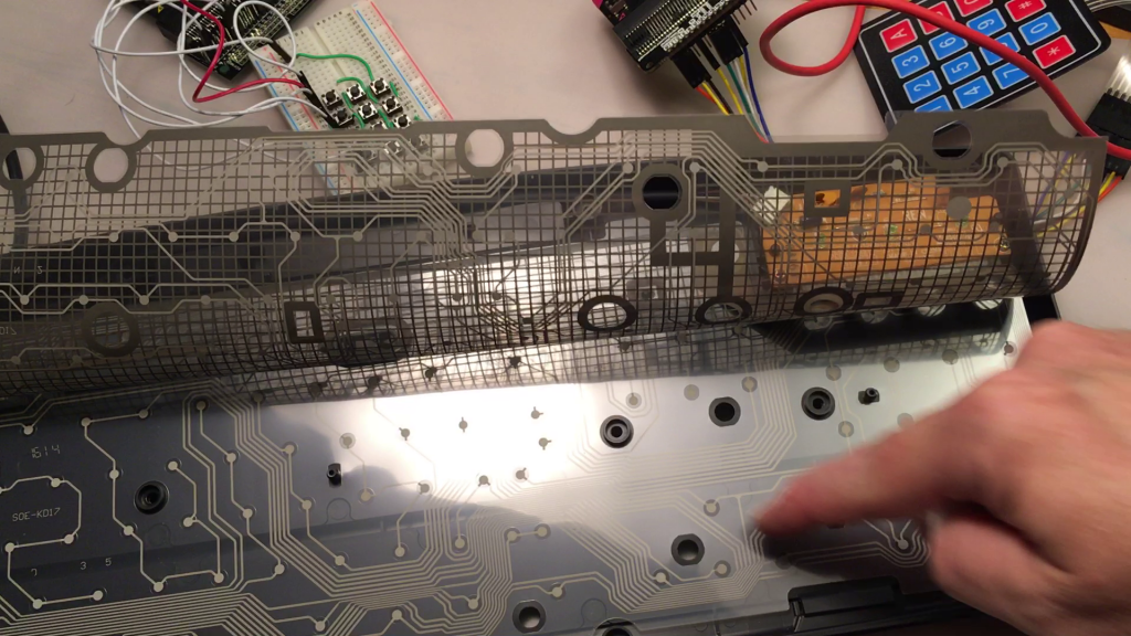
A standard computer keyboard contains around a hundred keys, so inside a keyboard these are usually arranged in a matrix as well, perhaps 6 rows of around 15 keys, meaning it needs just over 20 wires, rather than a hundred.
So a matrix is really a very neat way of arranging keyboard inputs on electronic devices.
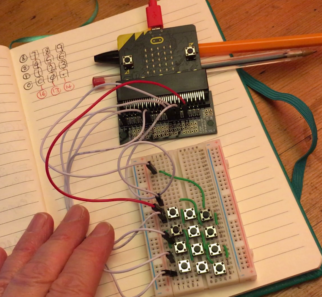
Making my own was fun and quite therapeutic! As every column in a breadboard is connected, and I only wanted to connect one side of each column of buttons together, I decided to stagger the buttons across the board. I used jumper wires to make the connections on each row and column. What you can’t easily see is that there are also jumper wires running underneath each button as well.
So, electrically speaking at least, I had created something that was the same as a real keypad matrix, even if I only had 12 buttons not 16.
But how to make it work?
I didn’t realise at the time that there was already a MakeCode extension for matrix keypads, which was lucky really as I had to invent my own way.
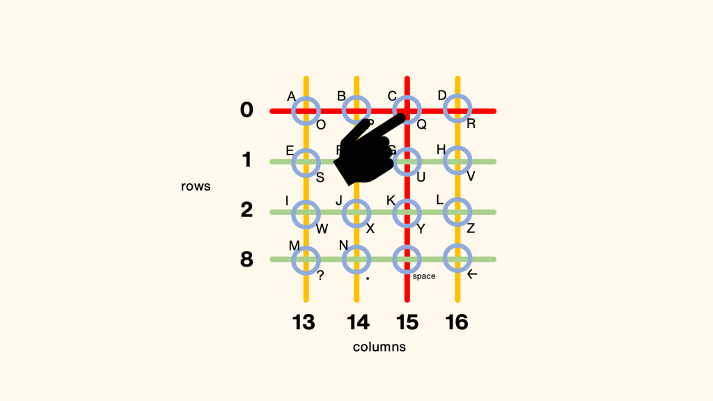
I knew some projects used different values of resistors to read pins using fewer than 8 wires, but I wanted to do it using as few components as possible. Using a breakout board on a micro:bit gives you access to extra pins, and I picked the following pins for rows and columns:
I avoided some pins that are also connected to the micro:bit’s own A and B buttons and elements of the LED display, as I want to able to use them in my projects.
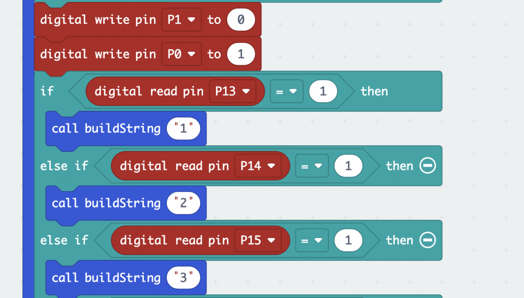
Using digital outputs and inputs on micro:bit pins is a simple way of detecting if a circuit has been made, so I created a loop in MakeCode that sends a digital output to each row in turn:
If it receives an input on any of the pins connected to the columns, then that means you must have pressed a button and the program responds accordingly, for example by showing a number or letter. The example below shows how the number 3 in my calculator or Mastermind game, or the letters C or Q would be detected in my communicator project:
I really didn’t expect this to work – but it did! I didn’t even have to add any code to debounce… it just seems to work!
Whilst making your own keyboard matrix out of buttons is instructive, it is very fiddly and time-consuming, and you can still learn a lot from using a pre-made keypad matrix. All you need to connect one of these to a micro:bit is a breakout board and some male to female jumper wires.
The code is quite simple to understand, and modify to suit whatever project you happen to be making.
What other fundamentals of computing can you expose and teach with the mighty micro:bit?

