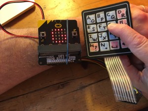
I learned a lot about how matrix keyboards work in a recent micro:bit project where I made my own out of some buttons and wire.
It’s much simpler, though, to use a ready made one and these 4×4 membrane keyboards were very inexpensive as a 5-pack. I set about wiring them up to a micro:bit and creating a simple calculator program in Microsoft MakeCode.
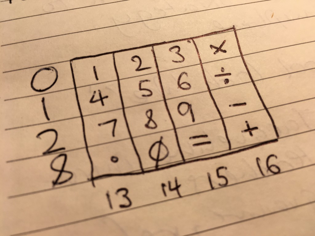
The keypad layout is not the same as a normal calculator, which has 7 8 9 in the top row, but it’ll do. I used the A B C D keys for the operators multiply, divide, subtract and add. I used the * button as decimal point and # as the equals key.
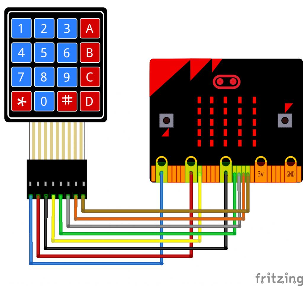
The first 4 pins on the keypad are the matrix rows, I connected them to micro:bit pins 0, 1, 2 and 8. (I skipped some pins which are also used for the display.)
The next 4 pins are the columns and I connected them to micro:bit pins 13, 14, 15 and 16.
If you have male-female jumper wires you don’t even need a breadboard to connect the keypad to your micro:bit, but you will need a micro:bit breakout board to access the pins.
To use the program, flash it on to a micro:bit. It will only add, multiply, divide or subtract two numbers. Each button press flashes the number on the screen, so pressing 2 2 will enter the number 22.
The program stores this as a text string, and when you press an operator key it assigns the number to variable a (also a text string).
When you press equals, it assigns the second number to variable b and then the calculate function converts the a and b strings to numbers using the parse to number block and carries out the appropriate calculation. If you miss the answer scrolling across the screen, you can press equals again to see it. Press button A on the micro:bit to clear, and button B shows you the currently stored calculation without actually giving the answer.
Here’s the code – it’s quite long but uses functions to try and make it more readable. The longest function is scanKeys which sends a digital signal out on each row in turn and reads the column pins to see if a connection has been made. I really didn’t expect this to work, but it seems to and doesn’t even require any de-bouncing.
Can you think of any other uses for a 4×4 keypad on a micro:bit? Some ideas floating round my head:
- noughts and crosses game
- Simon memory game
- controlling a robot
- making a micro:bit version of an early computer like a Kim-1 or an Acorn System 1
- electronic door lock
- alphabetical character entry using shift keys or 2 micro:bits and keypads for a radio / cryptography messaging project
.
Update: MakeCode extension
I’ve just discovered from @liou_jj in Taiwan that there’s a MakeCode blocks extension for these kinds of keypads: https://github.com/lioujj/pxt-keypad. I’ve not tried it, but it does look useful as it lets you set your own pin numbers so you can use it with other peripherals or avoid the pins used for buttons A and B or the display. I’d still recommend checking out my code above because it allows you to learn how keyboard scanning works, but an extension like this could make it easier to add keypads to your projects.
Text communicator
If you like this project, try my wireless text message communicator next!


Thank you for posting this. I am a US high school teacher and I used your information to wire my keypad and your scanKeys function as a starter for my own. Now I can teach this to my students. Here is a video of my calculator working: https://www.youtube.com/channel/UCAkXfAflNiNzDtjHys0VYgQ/videos
Hi Amy, that’s fantastic, so glad it’s been useful.
best wishes
Giles