Last week I made a binary adding machine out of 3 micro:bits to learn a bit about how computers work deep inside.
This week I’ve been inspired by Ben Eater’s 8-bit computer project. I highly recommend his videos if you want to learn how computers work at a really fundamental level. He has one project where he builds a simple computer on a breadboard using a 6502 processor, the same processor used by the first computer I ever used, my big brother’s Kim-1, as well as more famous machines like the Commodore PET, Commodore 64, Apple 2, BBC Micro, Atari games consoles and the Nintendo Entertainment System.
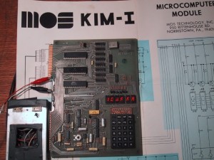 Very early (and relatively inexpensive) home computers in the 1970s, like the Kim-1 or the Science of Cambridge MK-14, were not even like the home computers of the 1980s. These were single-board computers, uncased like a Raspberry Pi is today but they didn’t, initially at least, hook up to your TV, nor did they have a typewriter keyboard. They just had hexadecimal calculator-like number keypads and simple LED displays of the kind you also found on the calculators of the day.
You didn’t program them in a high-level, easy-to-read language like BASIC or Python, either. You programmed them in assembly language: short very simple commands (usually in the form of 3-letter ‘mnemonics’) that each had their own hexadecimal number value that you entered using the keypad. This was very hard, slow and required a lot of planning and patience, but it meant that you were writing code that ran very quickly indeed on the ‘bare metal’ of the CPU (central processing unit). BASIC programs running on the same processors like the 6502 ran much more slowly, because your English-like BASIC commands had to be translated into something the processor could understand (machine code) every time it ran.
A very simple assembly language program might look like this:
start LDX #$FF    ; load X with $FF = 255
loop  DEX         ; X = X - 1
      BNE loop    ; if X not zero then goto loop
      RTS         ; return
All that program does is count down from 255 to 0 in a register – it doesn’t even output it.
Although it’s much harder to read that assembly language program than a BASIC or Python program, it’s easier to read than machine code. The processor can only understand numbers, so to actually enter the program above into a singe-board computer like the Kim-1 would require you to translate each instruction into its equivalent number code, so your program would become a string of hexadecimal numbers like
A2 FF CA D0 FD 60
that you had to enter using the calculator keypad. You would do the translation by hand using a chart, or if you were lucky and had a more advanced computer, a program called an assembler would translate the assembly language to machine code for you.
Ben Eater’s breadboard computers are like this, and as well as his 6502-based project, he also makes his own processor using logic gates on breadboards to build a really simple computer, and that’s what fired my imagination. Could you create your own processor with a small instruction set using a micro:bit?
This is what I came up with.
A micro:bit CPU
I decided my micro:bit CPU would be a 5-bit computer, rather than 8-bit as you might expect. This is because I want to show the contents of memory, instructions and so on using the LEDs on the micro:bit’s display, which is made up of 5 rows of 5.
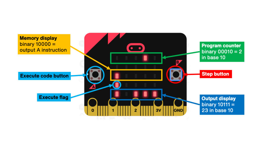
The top row of LEDs shows the program counter as a binary number. Dark LEDs are zeroes, lit LEDs are ones. Here the number is 00010 in binary, or step 2 in base 10. This counts up as we step through the program.
Unlike a real CPU, we’re not going to use a clock to automatically step through instructions, we’re going to do this manually by pressing button B.
The middle row shows the contents of the memory at the address shown on the top row, again as a binary number. So here we see that memory location 00010 contains 10000.
The bottom row is the output. This is blank until we write something to it, which as it happens this program just has, because 10000 is an instruction code to write the contents of a register (like a variable) to the display output.
How do we know 10000 means ‘write contents of register A to the output display’? Because that’s how our micro:bit processor is designed. Even simple microprocessors have dozens of instructions, but ours is only going to have 4:
It’s only got 4 because remember I’ve decided only to use a 5-bit word, and if I’m going to be able to include any meaningful address data I think I need at least 3 bits to store the address (the red Xs in the table above). That only leaves 2 bits for actual instructions.
You can think of the first two binary digits as the opcode (operation code, or instruction), and the last 3 digits as the operand (the data that will be manipulated by the opcode).
I’ve decided my processor can load the contents of a memory slot into a register called A. This is, in effect, a variable. It can also add the contents of another memory location to it. It can output the contents of A. Finally, the Halt instruction tells it to stop executing the program. We need this because we want to use memory slots after our program code to contain data like the numbers we’re going to add, and we don’t want the processor trying to execute the data as if it were an instruction.
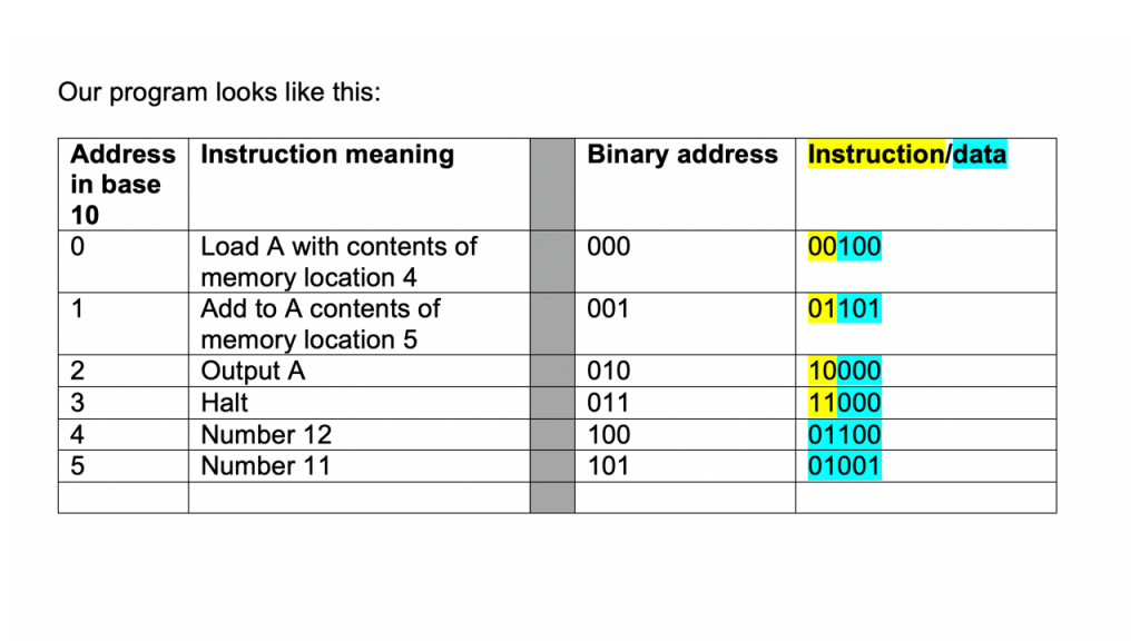
The code
It loads the contents of memory location 4 into register A. It then adds the contents of location 5 to it, shows it on the display output and stops. In effect, it’s adding 12 and 11 and showing the result as a binary number on the micro:bit’s LED display.
Try it out in the simulator
The code for this project is in this HEX file (right click and ‘save link as…’ or ‘save target as…’ to download it). You will (at the time of writing) need to load it in the beta version of MakeCode because it uses some new blocks.
Press button B to step through each memory location to check the program. Reset the simulator and press button A to switch on execute mode. You should see the execute flag light come on. Now when you step through the program using button B it will execute any data as instructions until it reaches a Halt instruction. Keep pressing button B and you should see the number 23 appear in the bottom row as binary 10111.
A little bit of history repeating
4 instructions is a very reduced instruction set, but Reduced Instruction Set Computers (RISC) were, and are, a thing. In the late 20th century, people realised that processors with reduced instruction sets were faster and used less power, meaning you could run them on batteries in portable devices. One company doing this was a British one called ARM. They designed the processor that went in early mobile computers like the Apple Newton. Today almost every smartphone has an ARM-designed CPU in it, as indeed does the BBC micro:bit.
You may not know that the A in ARM originally stood for Acorn: Acorn RISC Machines. Acorn made the BBC Micro, a computer widely-used in UK schools in the 1980s. It was also quite a popular home computer, and it used the same 6502 processor used by the Apple, Commodore and Atari computers of the time. The BBC Micro was part of a digital literacy scheme including TV programmes, and this was echoed by the 2016 BBC Make It Digital campaign which introduced the micro:bit. So ARM were involved in both projects, and indeed they are founding partners of the Micro:bit Educational Foundation.
How does it work?
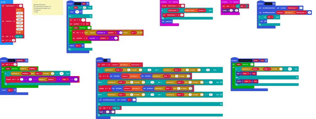
I’ve used what is still at the time of writing a beta version of MakeCode for this project because it allows functions that pass back parameters. I go into a little more detail in the video, but the main elements are:
- the memory is made up of binary numbers stored as text strings in an array
- the PgmCounter variable tracks where you are in the program – this is a normal base 10 MakeCode variable
- functions convert between base 10 (denary) integers and binary number strings and vice versa, returning a value
- a function displays any binary number string on any specified row on the LED display
- the CPU function contains the code that fetches, decodes and executes instructions just like in a real processor
Here’s the function that converts from binary to base 10. The CPU function uses this to translate binary memory addresses and data into base 10 so we can use normal MakeCode maths functions and array addresses. Let’s unpack how this works.
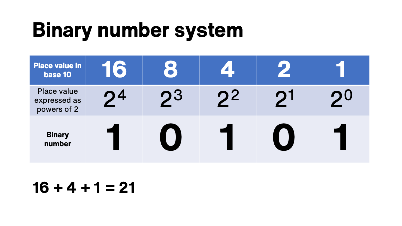
The binary number is held as a text string, so the loops steps though every character for however long the number is. The easiest way to convert from binary to base 10 is to identify the place value for each digit and add them up:
The function does just that. It keeps a running total of the base 10 value in the dec variable.
Notice that each place value (1, 2, 4, 8, 16 etc) can be written as powers of 2. 1 is 2 to the power of 0, 2 is 2 to the power of 1, 4 is 2 to the power of 2, then 3 and 4. The function uses that fact to do the conversion in very few blocks of code.
It uses char from text at index to look at each binary character in term.
If it finds a ’1′ character, it uses its place in the binary number string to work work out which power of 2 to add to the base 10 total.
Because it’s going from left-to-right, from most significant (largest) bit to smallest, we need to a bit of jiggery-pokery to reverse the list and work out the power needed.
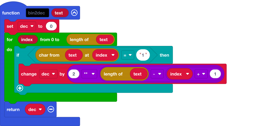
(This is a simplified and improved version of the function actually used in the project).
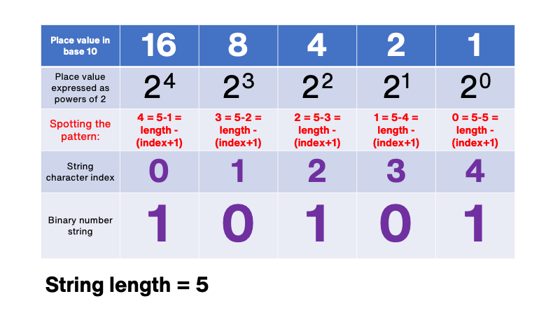
I wasn’t sure how to do this, so I wrote out a table a bit like this to see if I could spot the pattern and find how to convert the location of a digit to its place value as expressed as powers of 2. If we can spot a pattern, we can write a compact bit of code to do the conversion:
So, we need to convert the character string index to the power, convert 0 to 4, 1 to 3, 2 to 2 and so on – and it would be neat to do this for any length string.
The pattern I spotted was that the power is equal to the length of the binary number string minus the index plus 1. We have to add 1 because string character indices are zero-indexed – the first character is character number 0.
Next steps
Let me know if you have ideas for improving this or if you find it. useful for understanding or teaching how CPUs and simple systems work.
One idea I have is to split the instruction and address data, allowing many more instructions – 32 in fact – and the ability to create much more useful programs that have more maths functions and which can include ‘if’ statements by jumping to different memory locations depending on the results of calculations.
You may also like…
If this sparked your interest, check out this awesome project: https://github.com/veryalien/mycobit. It’s a 4-bit micro:bit CPU, written in Python, that you can program using the micro:bit’s own buttons, so it’s self-contained and doesn’t need a computer. It has a useful instruction set and gives access to GPIO pins. I look forward very much to playing with this, and perhaps magpie-ing some instruction set ideas for the next version of my MakeCode micro:bit CPU.
And check this out! I just learned about another micro:bit CPU program written in Python (and indeed in Croatian) by Ivan Bosnić that uses actual written opcodes / mnemonics: https://github.com/bosnivan/CPPU. If you don’t speak Croatian, you can still work out what the instructions do.


Muy bueno el proyecto pero su cpu no es de CPU micro: bit de 4 bits seria de 4 bytes
si no podria poner en este ejemplo la Inst 3
Page Byte Inst Data Comments
0 0 1 1 Show the data value 1 on the mycobit display . . . . O
0 1 3 0 HALT – jump backwards 0 bytes, so that the program stops
un bit solo tiene dos estados 0 o 1 esa instruccion es un byte
Saludos
Hola José,
Es bueno saber de ti. Disculpe, no hablo español así que estoy usando DeepL para traducir para mí. El autor del proyecto mycobit, ‘veryalien’, lo describe como un sistema de 4 bits porque cada palabra de instrucción comprende 4 bits. Yo llamo a mi sistema un sistema de 5 bits porque cada una de mis palabras tiene 5 bits de largo – un número binario de 5 dígitos. Creo que un byte debe consistir en 8 números binarios.
¡Espero que eso ayude!
Mis mejores deseos…
Giles
Traducción realizada con la versión gratuita del traductor http://www.DeepL.com/Translator
Hello, if I totally share that a byte must consist of 8 binary numbers, I am struck by that example in which each word is made up of 4 bits and I find those values in the examples.
sorry for confusing your system with mycobit “veryalien”,
I thought it was your repository many successes with the project
Regards
Thanks for your publication.
You mention MyCobit here in this article, and it seems your processor implementation in MakeCode is the closest I have seen to MyCo. I published a few books about MyCo, and you find them here
as part of my bookshelf https://www.amazon.co.uk/Juergen-Pintaske/e/B00N8HVEZM
There are 3 about MyCo – the last one actually works completely on paper – ok, the LEDs are not flashing then …
I always wanted to find out, how difficult it would be to implement MyCo – or TPS as the original name was – in Make Code
In addition to the books there is much information here
https://www.facebook.com/groups/269499491046124
and much info elsewhere is in German – Burkhard Kainka invented this computer
controlled by 3 switches as keyboard
and using 5 LEDS as Display
and OUTPUT.
Willie extended it to control servos as well;
have a look.
This might be an interesting exercise to do a conmplete processor system in MakeCode epldfpga@aol.com Juergen
unfortunately the veryalien gihub page seems to have vanished.
But much of it you find here http://www.elektronik-labor.de/Literatur/MyCo.html
and in other places on Burkhard’s website
https://www.elektronik-labor.de/Lernpakete/TPS/TPS0.html
and some parts in English , her regarding microbit
https://www.elektronik-labor.de/Lernpakete/TPS/TPS45.html
and an article.
Enjy as we do.
Or see more on our facebook page https://www.facebook.com/groups/269499491046124/about
MyCo TPS veryalien github is back as before
see Links here
https://www.elektronik-labor.de/Lernpakete/TPS/TPS45.html