I’m going to how to show you to turn two or more micro:bits in to a binary adding machine, using the same code on every micro:bit.
The ability to add two numbers together is a fundamental building block of any calculating machine. If you can add, you can multiply as multiplication is repeated addition. If you can add, you can probably subtract, and that means you can do division as well, as division can be thought of as repeated subtraction.
But the ability to add numbers is ALSO fundamental to building computers. As well as solving maths problems, adding numbers enables computers to find data in memory, step through lists of instructions as well as more exciting things like moving a space ship across your screen in a game.
Electronic circuits that can do sums – and do them very quickly – are called adders. Lots of them are wired together to form the Arithmetic Logic Unit in the processor at the heart of every computer, tablet, phone and many electronic devices like TVs and washing machines.
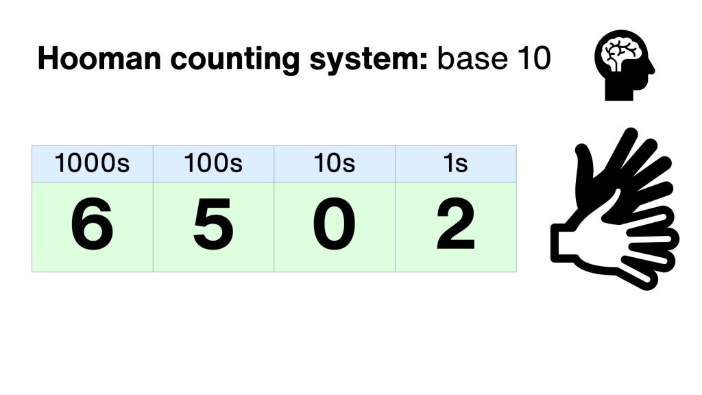
Humans usually count in a system based around the number 10 – because we have 10 fingers. We use 10 different symbols, 0 through to 9 to record numbers. Each column is worth 10 times more than the one to its right. This is called base 10, or denary.
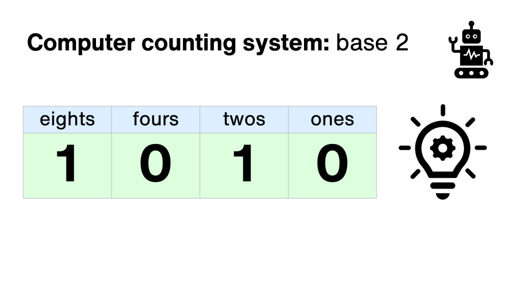
 Computers, on the other, er, hand, use the binary system, which just uses two symbols: 0 and 1. This is because computers are made up of millions of tiny switches, and a switch can be used to store binary numbers: off means 0, and on means 1. This is why the on/off power symbol used on many devices is a zero with a 1 inside!
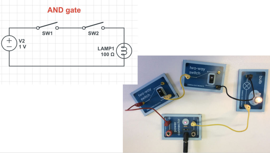
So switches form the circuits that make up computers, by making logic gates. Logic gates take simple binary inputs, on or off, 0 or 1, and make different outputs. Some are simple, like AND gates. These give an output only if both its inputs are switched on.
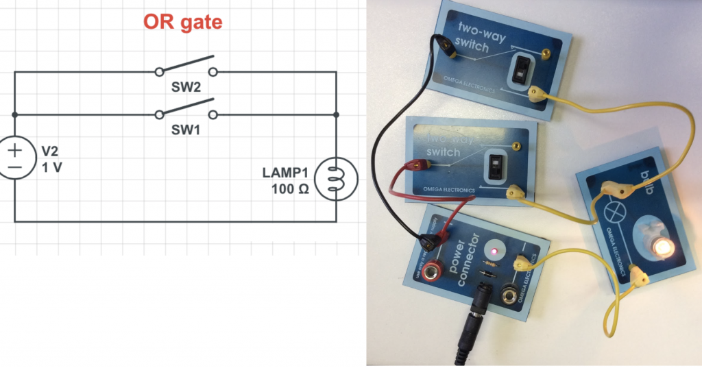
The OR gate, on the other hand, will give an output if EITHER of its inputs are turned on.
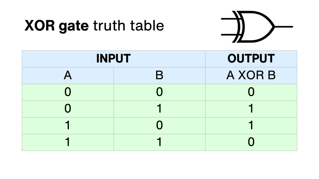
The EXCLUSIVE OR gate gives an output if either input is switched on – but not both.
Why do you need to know that? Because logic gates like these make up computer memory but also are the building blocks of the Arithmetic Logic Unit, the part of the processor that does all the maths, all the number crunching.
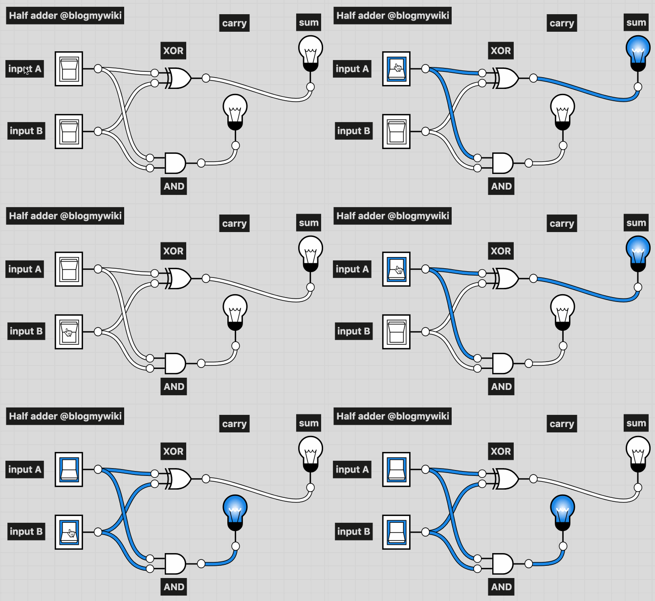
If you connect up an AND logic gate and an XOR gate, you can use it to add two binary numbers together. This is called a half adder. Each switch is a 0 or 1 depending on whether it’s turned on or off. The lights show the sum – if a light’s on it’s 1, if it’s off it’s 0.
You’ll see that both switches off – 0 + 0 – means no lights are lit – binary 00.
If either switch A or B is, the sum light is lit, but not the carry – binary 01.
If both A and B are switched on, we’re adding 1+1. The answer is 10. Why 10? Well it doesn’t mean ten, it means no units, and 1 two – the answer to 1+1 is 2!
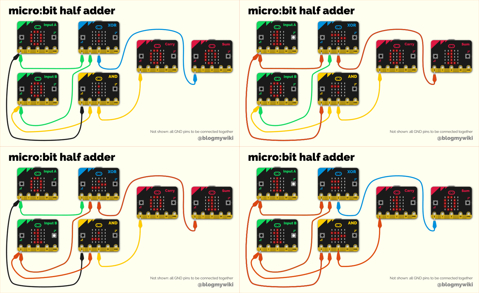
Last year I made a project using 6 micro:bits to simulate a half adder – though you could replace the two input micro:bits with real switches to use just 4 micro:bits instead. We have separate micro:bits acting as an AND and XOR gate, taking real electrical signal inputs, processing the inputs and producing outputs that add two numbers together.
Of course a micro:bit contains thousands of actual logic gates, so it IS a bit crazy to turn one into a single logic gate, but it’s interesting to code it, and connect all the parts together to make the most fundamental part of any computer system.
That’s only adding two single-digits together, though, and it uses a lot of micro:bits. So I’ve made another project – a full adder on a single micro:bit.
A full adder has not two, but three inputs – A, B and a Carry In. As well as the two numbers you’re adding, the Carry In takes the Carry Out from a neighbouring adder, just as you add in any numbers you carry when doing column addition in base 10 arithmetic.
So you can add together as many full adders as you like to allow you to add really big numbers together. Every single adder you, er, add, makes the largest number you can add twice as big.
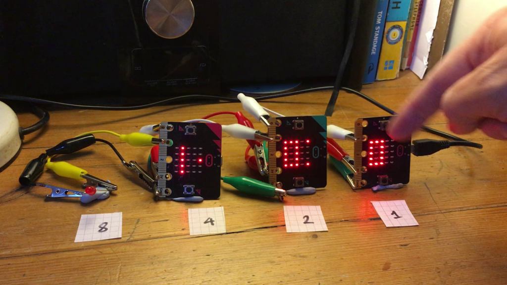
So, here’s how you connect it together: use as many micro:bits as you like, and the same code goes on every one. Turn them on their side. Pin 1 is the Carry Out, so connect it to pin 0 – the Carry In – on the micro:bit to its left and keep going until you run out of micro:bits.
That leaves us with one carry out left over, no matter how many micro:bits we use. But we don’t need to let it go to waste! If you have an LED lying around, connect its long leg (the anode) to the final carry out, and its short leg to GND. While you’re there, connect all the GND pins together, to complete the electrical circuit.
You could power each micro:bit individually from batteries or USB, and indeed it’s safer to do that, but I’ve been a bit cheeky here. I’ve only powered the far micro:bit on the right, and powered all the others from it by joining their 3 volt pins together. If you connect many more than 3 together this probably wouldn’t work.
Here’s how to use it.
The top row of A switches make up the first number we’re going to add. The LED dot in the top right of each display shows you if the switch is on or off, it toggles every time you press it.
The row of B switches across the bottom make up the second number, and the LED in the bottom right shows you if it’s on or off.
To add 1 + 1 set the top and bottom rows to 001 and you can see the result: 010 in binary, which is 2 in base 10.
You’ll see another light has lit up on the micro:bit in the 2s column. That’s to show that it’s received the carry bit from its neighbour.
Ok, let’s do some more adding. 2 + 2. That 010 and 010 in binary. And the answer is 100, we’ve got no units, no twos and one four.
How about 5 + 5? That’s 101 and 101 – the answer is ten of course in base 10. We only have 3 micro:bit numbers, but notice our carry LED is now lit on the far left, meaning the number is 1010 in binary. One eight, and one two. 8 + 2 = 10. The right answer!
Let’s look at how my micro:bit full adder works. The same program goes on every micro:bit in the adder, no matter how many you have, just like a real adder uses identical circuits chained together.
It uses two variables to store the value of A and B, but instead of giving them numerical values of 0 or 1, I’m using TRUE or FALSE. TRUE means 1 and FALSE means 0. I set both to FALSE, off, zero at the start of the program.
Calling 0 false and 1 true is also common when talking about logic gates and circuits. The charts that show how logic gates work are called truth tables.
Another reason for using true and false for 1 and 0 here is that it makes it really easy to flip each variable’s value when you press a button with ‘set A to not A’ and ‘set B to not B’ – if each variable is 0 or 1, it flips to the other value when you press the button.
To keep the code easy to follow, I’ve made a function – a subroutine – to turn the relevant LEDs on and off to show the values of A and B.
As with many computer programs, the real business goes on inside the infinite loop, the forever block in MakeCode.
I’ve used another function here as a subroutine – this one keeps checking if it’s receiving any carry bits from next door. If it is, it lights the carry in LED and sets the carryIn variable to True. If not, it turns the LED off and carryIn’s value will be False.
Now, the real heart of the program is in the big if… then… block.
Rather than implementing it purely as the wired logic gates, I looked at the truth table for a full adder and worked from the bottom up.
If all the inputs are turned on, we’re adding 1 + 1 + 1 we have 11 in binary, so we need to show 1 on the display, and turn on the carryOut signal so it gets added to the next column.
If A and B are 1 and Cin is 0 (not Cin means Cin is false, or 0), we have 1+1 = 10 in binary – we need to show 0 on the display and turn on the carry out signal.
If either A or B is 1 AND Cin is 1, it’s the same thing, 1+1, so we provide the same output, 0 in the display and carry one out to the next column.
We’re running out of options now. If any one of A, B or Cin is 1, we only have 1, so let’s show a 1 on the display and turn off the carry out signal.
If none of those cases is true, we must have no numbers at all, and 0 + 0 + 0 is 0 in any counting system, so the display shows 0 and there’s nothing to carry out to the next column.
As my micro:bits are on their sides, I’ve used functions to draw the sideways 0s and 1s on the LED display.
If you make an adding machine using this program do let me know, or if you have ideas for further improving it!

