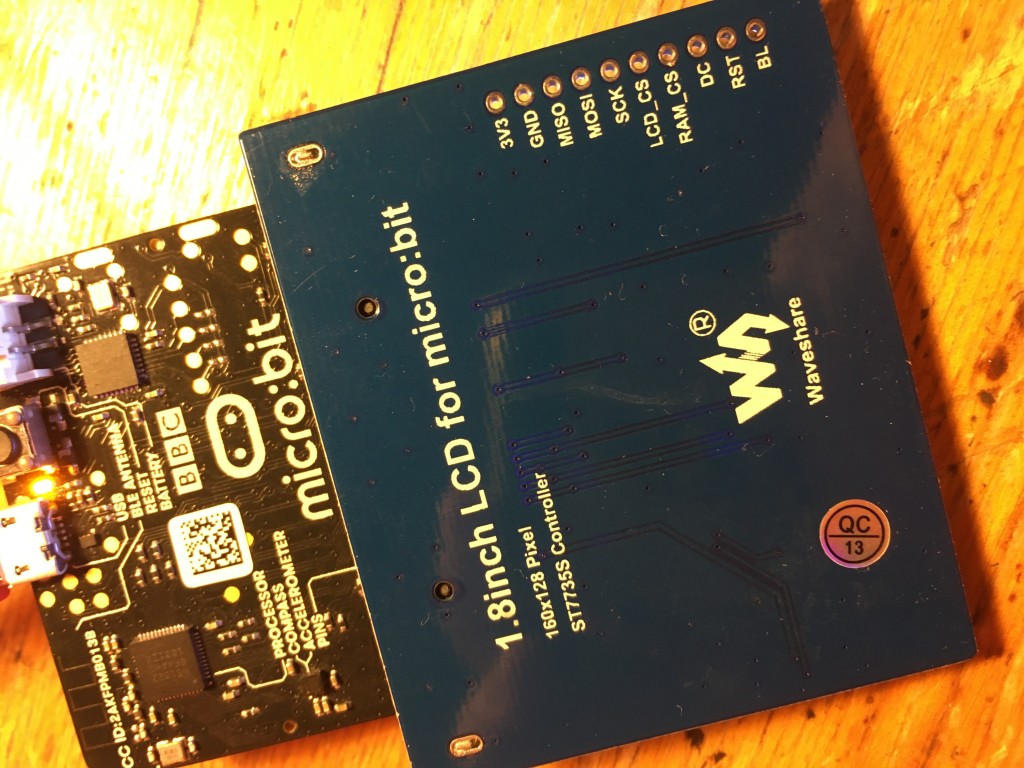
I love displays so I couldn’t resist this £10 Waveshare colour LCD that plugs straight into the micro:bit’s edge connector. It’s small, 1.8 inches across, and with a resolution of 160×128 pixels, but just the right size to match a micro:bit.
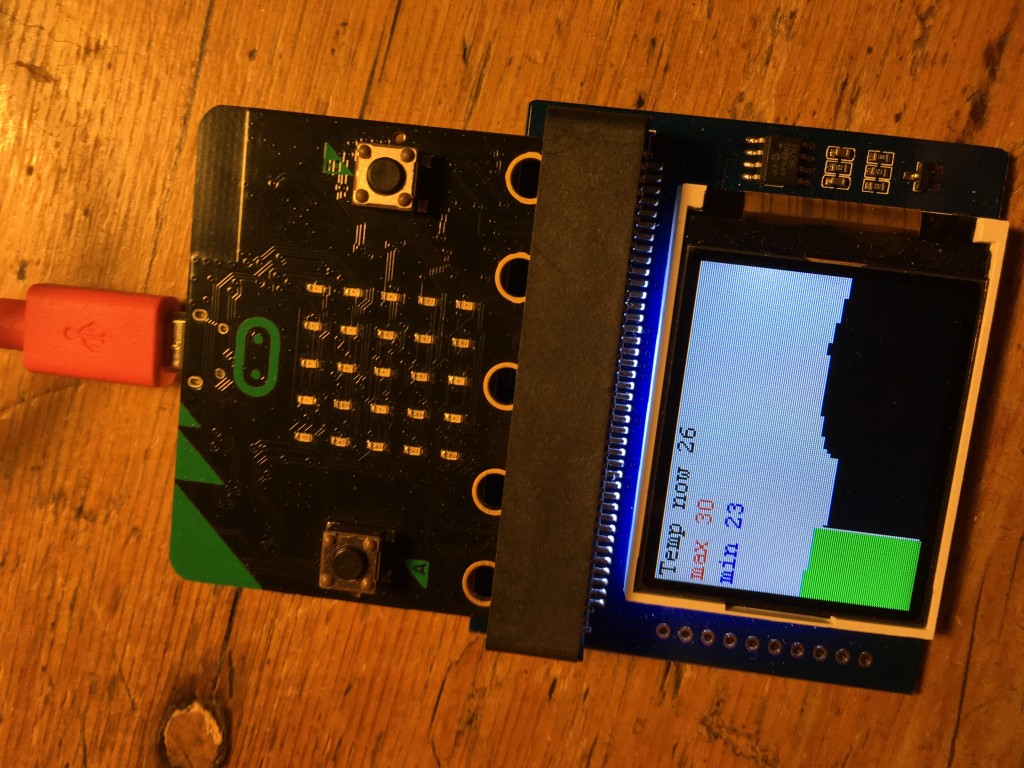
Getting it working was a bit of a challenge, but eventually I found what I needed to make a thermometer that keeps track of maximum and minimum temperatures and plots them in real time on a graph moving across the screen.
To get it working you have to use the old MakeCode editor: https://makecode.microbit.org/v0/
You also need to add the driver by clicking on the cog and then ‘Add package’, pasting in this URL: https://github.com/waveshare/WSLCD1in8
The documentation, once I’d found it, isn’t brilliant, but there’s enough to get you going.
What I really like about this device and its driver is that it doesn’t entirely protect you from the low-level stuff that goes on to make LCD displays work, and because of this you may learn more than you might just working with normal graphics on a computer-based programming language. The fact that we’re programming a micro controller and tiny LCD display means we get a bit deeper into the hardware-software interface, closer to the metal, but not so close as to be too scary.
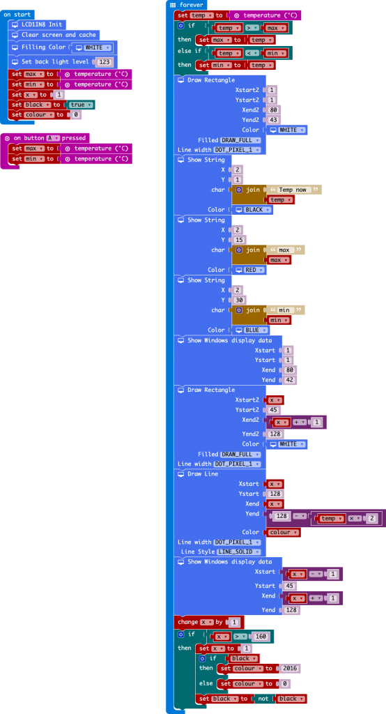
For example, you have to begin by initialising the display, clearing and allocating memory for your graphics. If you draw a line, circle, box or text on the display, nothing happens. You have to update the display. You can do this with the ‘send display data’ block, but this updates the whole display, which is slow. Better – and much quicker – only to update the part of the display that’s changed, and you can do that with the ‘Show Windows display data’ block, specifying the co-ordinates of the area you want to refresh. In the thermometer program below, I could speed the program up by only refreshing the numbers when they change, for example, or refreshing smaller parts of the display. This is a nice example of the kinds of considerations you have to make when working at a low level with meagre resources.
I also learned something new about how colours are displayed on LCDs. The MakeCode extension gives you a few pre-defined names colours, but I was curious to know more and noticed that the HEX colour codes in the driver were really odd. I expected 3 values, 1 red, 1 green, 1 blue. But instead there were four HEX numbers. White was FFFF, black 0000 which is what you’d expect, but red is F81F, green 07E0 (2016 in decimal, see code below!) and blue 001F. What’s going on?
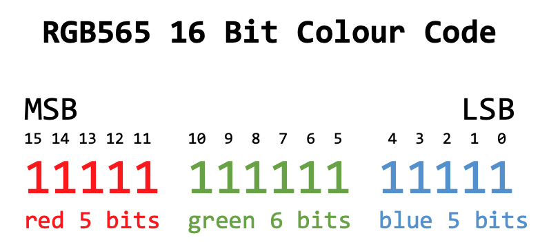
It turns out that TFT LCD displays often use something called RGB565 16 Bit colour coding. This defines colours in an odd scheme where the red and blue channels get 5 bits each, and the green channel gets 6 bits:
Why give the green channel an extra bit? Because the human eye is more sensitive to green light (and shades of green), and so it makes sense to use the extra bit where it can do more good. I found this colour picker to help select 16 bit RGB565 colours.
This LCD display also brings its connections out to unsoldered holes where you could add a header to connect to a breadboard and another micro-controller such as an Arduino.
What shall I do with this next? Some sort of game seems obvious, but is it fast enough?!
Code for program to plot temperature readings alternately in black and green across screen and track current, maximum and minimum temperatures recorded. The rectangles are drawn to erase previous numbers and graph plots.
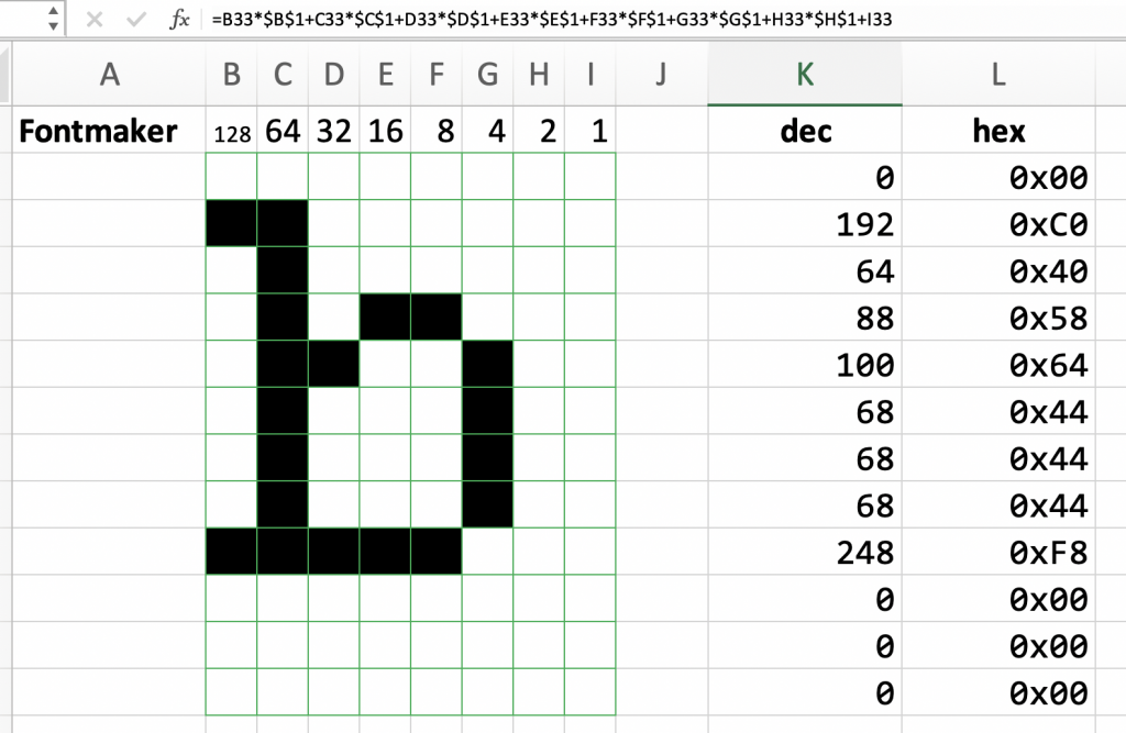
I also got fascinated with how drivers for this – and the OLED display I tried next – encode fonts and graphics, so I made myself a spreadsheet to turn sequences of binary numbers (with 1s automatically shaded black) into hex numbers. I learnt a lot this way and there could be a lesson here around digital representaion of images:
And here’s another project I made, live-plotting accelerometer readings:

Can you explain how the “partial refresh” works? I’m trying to figure it out but it’s not working for me. Do I first defined a “block” that I want to refresh and then do a refresh?
It’s been a while since I played with this. Looks like I wrote some data to the screen then used the ‘Show Windows display data’ block with specified co-ordinates of the area I wanted to refresh.
Is there a way to upload images without doing it bit-by-bit? I’d like to be able to just select a file.
Not that I’m aware of – this lovely little display needs some new drivers I think!
Not sure what I’m doing wrong, but (I’ve tried it on : ipad, phone and pc) after adding the support and trying to compile the code, I’m getting the compilation error. It happens even with a single line containing the WSLCD1IN8.LCD.Init().
Any idea what’s wrong?
Hi Marek – are you using the old MakeCode editor? ( https://makecode.microbit.org/v0/ ) I’ve not used this display for a long time, but a year ago that was a requirement to make the extension work.
best wishes and good luck,
Giles
For some reason my blocks are much more different than yours. I don’t have the block “clear screen and cache”.
Hi Daniel – it’s a long time since I tried this screen. Did you add the extension to the v0 editor?
I was wondering if you could make a game with this cause I’m having a hard time understanding all of this and if you made a game I think it would help a lot. Thanks man. :)
Hi there – unless there’s a new MakeCode extension for this display, I don’t think I’ll be doing any more with it – one day perhaps!
ok thanks