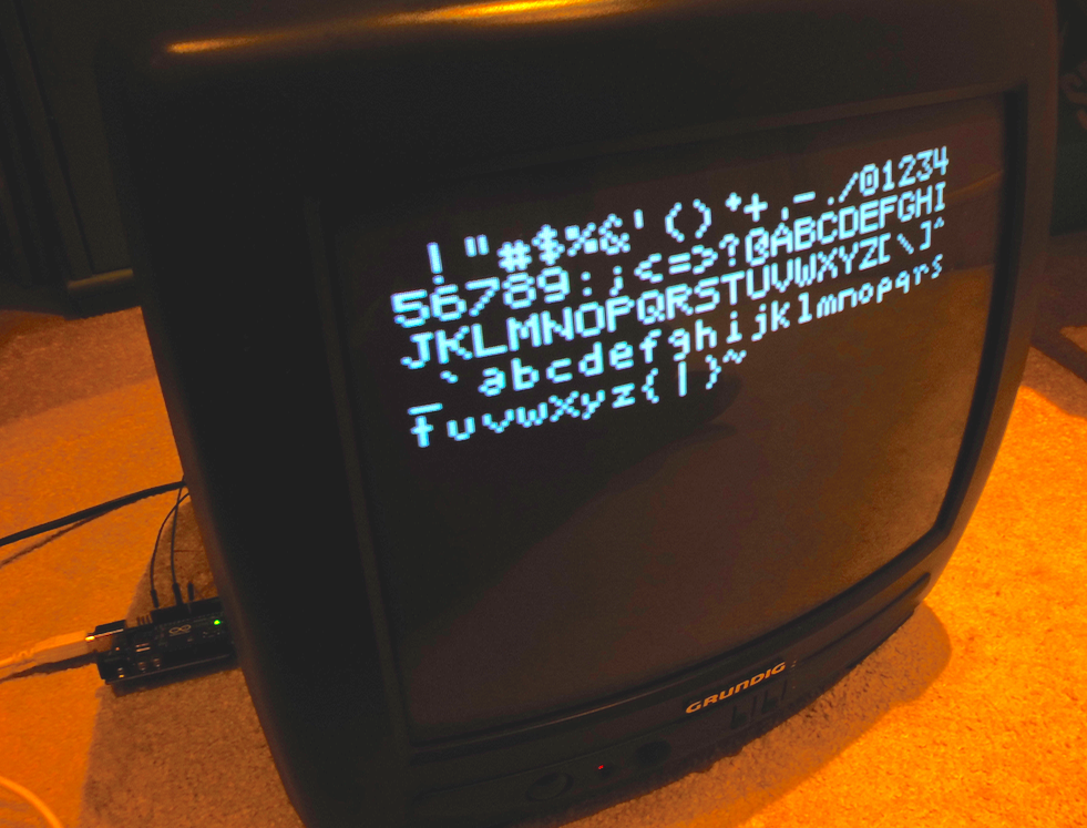
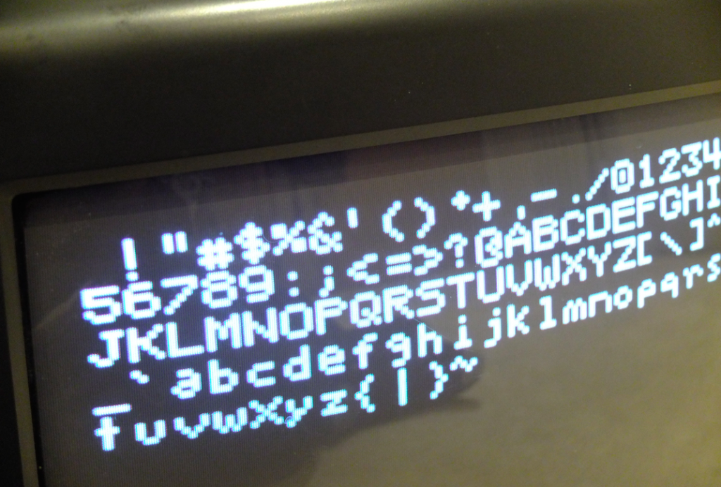
 It’s supposed to be easy – 2 or 3 resistors and you can get your Arduino micro controller to produce low-resolution black and white composite video. Well, it wasn’t for me. It took me hours to get it working, but I finally cracked it. It’s possible I was unlucky, stupid or possibly both – but I’m writing it up before I forget how I did it and in case someone else has the same problem.
I tried about 4 different projects on different web sites which all broadly worked the same way: you connect a couple of resistors to some pins on the Arduino, wire them up to a phono plug, install the TV Out library in the Arduino IDE, compile and flash the code and off you go.
I could not get any of the sample code to compile in the current version of the Arduino IDE. I lost track of the different error messages I got. I’d make progress then something else would break. Googling error messages kept telling me to install the TV Out libraries – which I had.
Spookily I’d decided to try an old version of the Arduino IDE at the same time that @gadgetoid on Twitter made the same suggestion. In the end I compiled and uploaded working code using version 1.0.1 of the Arduino IDE on an old Lenovo Ideapad running MacOS X 10.6 (Snow Leopard). I could not get any demo code to compile using the current version of the Arduino IDE, nor could I install an old version of the IDE on my MacBook because they required older versions of Java. Thank goodness for the old hackintosh!
I used:
- An old Arduino UNO (perhaps its age was part of the problem)
- a phono / RCA plug
- some jumper wires
- a small breadboard
- A 470 ohm resistor
- A 1K ohm resistor
- A 75 ohm resistor
- An old laptop to program the Arduino
- an old CRT TV with a composite video input (most modern LCD TVs have such inputs – or you can use a SCART adaptor)
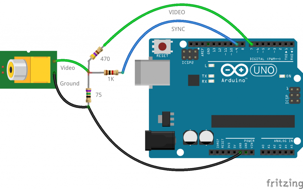
Here’s how I wired it up. (In the photo there are 4 resistors not 3 because I lacked a certain value and wired two together in series).
(I am grateful to microcontrollerelectronics.com for hosting the Fritzing diagram of their project – the only difference here is that I had to move the green video wire to pin 7 (not 8) as I am using an Arduino UNO not a Leonardo as they did.)
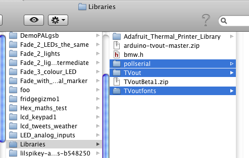
The version of the TV Out library that I think I used finally (there were so many) was TVOutBeta1.zip – unpacked the zip file and put the 3 folders pollserial, TVout and TVoutfonts in the Arduino/Libraries folder like this:
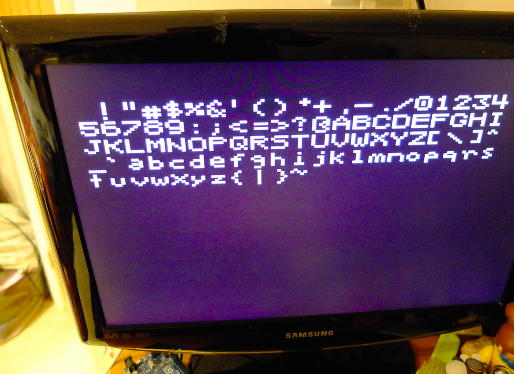
This is the code that finally worked – I’m afraid I can’t remember where I copied it from now, I had so many snippets of code on the go. If it’s yours I will of course credit and link (or remove it).
Here it is working on a modern LCD TV rather than the retro CRT model at the top of the page:
Now I wonder if I can remember why I wanted to get this working in the first place..?
#include <TVout.h>
#include <fontALL.h>

TVout TV;
unsigned char x,y;

void setup()  {
  x=0;
  y=0;
  TV.begin(PAL);	//for devices with only 1k sram(m168) use TV.begin(_NTSC,128,56)
  TV.select_font(font6x8);
}

void loop() {
  TV.clear_screen();
  x=0;
  y=0;
  for (char i = 32; i < 127; i++) {     TV.print_char(x*6,y*8,i);     x++;     if (x >= TV.char_line()) {
      y++;
      x=0;
    }
  }
  TV.delay(1000);
  TV.clear_screen();
  TV.println("Fill the Screen\nPixel by Pixel");
  TV.delay(1000);
  TV.clear_screen();
  for(x=0;x


Giles –
Thank you for this post. It is very clever. I love the simplicity of it.
Harish
The source code that is shown ends prematurely.
Wolfgang
So it does! I can’t find the original file, must be on another computer. Will keep looking.
Looks like you haven’t included the actual font you’re calling on. Could this be the issue?
#include
err. Code got mangled. Anyway,
include font6x8 dot h
It’s here in full:
https://github.com/Avamander/arduino-tvout/blob/master/TVout/examples/DemoPAL/DemoPAL.pde
For anyone building this, I used the schematic listed in this article as well as the listed TVOutBeta1.zip libraries. In the TVout folder in the attached libraries is an example folder. I used the example “DemoNTSC” and copied the files into a folder under arduino called “DemoNTSC” and I renamed the DemoNTSC.pde file to DemoNTSC.ino. I uploaded that to an arduino nano using pin 7 for video and pin 9 for sync and the example worked on the first try. I am using this in my Pace Arrow motor home to display information on the monitor I have for my backup camera which has 2 AV inputs. AV2 is used for the backup camera, but AV1 did nothing other than display “No Signal” on a blue screen when driving. Now I have it displaying the status of my TV antenna mast whether it is up or down. I am planning to incorporate other things like the status of my electric step for the entry door (in or extended), and possibly my leveling jack status once I get those fixed. Here is a video showing what I have so far. https://www.youtube.com/watch?v=6Y70Jyy1D04 To do the Pace Arrow logo I used a image to C hex converter from this website, which worked perfectly. https://www.digole.com/tools/PicturetoC_Hex_converter.php
Many thanks for this post.
I was searching for a project like this.
I have a 3 inch lcd from my car rear view camera. It has 2 analog video inputs. Can I use this display in arduino or nodemcu project. Don’t want to spend in purchasing a i2c display.
You can get better resolution by using the serial port Tx line in master SPI mode 0, see this YouTube video for an example, and a link to download the code in the video description.